IPC-TM-650 EN 2022 试验方法--.pdf - 第696页
Figure 1 IPC -B-25A T est Board Material in this T est M ethods Manual was voluntarily establis hed by T echni cal Committees of IPC. Thi s mat erial is a dvisory only and its use or adaptation is entirely voluntary . IP…
7 Notes
7.1
The design of the thermal cycling system must be flex-
ible enough to allow for an extremely high rate of temperature
change and for the rate of temperature change to be deter-
mined. Some issues to consider are as follows:
• Thermal mass compensation capability (energy vs. time)
• Environmental control capability (heating and cooling)
• Reproducibility of parameters
• Transfer speed (if applicable)
• Heating ramp rate
• Cool down rate
• Programming capability
• Profile memory
7.2 Suggested Drawing Note
As this method addresses
assembly issues with printed boards, it is recommended that
the user of the printed board establish a drawing note in the
procurement documentation to provide the printed board fab-
ricators with guidance relative to the intended reflow process
of the printed board. An example of such a drawing note is
provided as follows:
XX. IPC D COUPON TESTING
A. COUPONS SHALL INCLUDE COMPONENT (A), VIA (B)
AND ALL PROPAGATED B STRUCTURES IAW IPC-
2221B APPENDIX A.
OF EACH COUPON DESIGN
BE TESTED PER MANUFACTURING PANEL.
B. THE IPC D COUPONS
BE SUBJECTED TO 6
REFLOW SIMULATIONS IAW IPC-TM-650, METHOD
2.6.27 USING THE [
]
PROFILE. ACCEPTANCE CRITERIA
BE < 5%
CHANGE IN RESISTANCE.
C. AFTER REFLOW SIMULATION TESTING, THE IPC D
COUPONS
BE SUBJECTED TO 100 THERMAL
SHOCKS IAW IPC-TM-650, METHOD 2.6.7.2 FROM
-55C TO [MINIMUM OF (
), OR
(
), OR
]. ACCEPTANCE CRITERIA BE < 5%
CHANGE IN RESISTANCE.
Parameters in should be tailored to each
application.
Number
2.6.7.2
Subject
Thermal Shock, Thermal Cycle and Continuity
Date
3/2020
Revision
C
IPC-TM-650
—
2
SHALL
SHALL
230
℃
,
OR
245
°C,
OR
260
SHALL
SHALL
LAMINATE
TG
-
10
REFLOW
PEAK
TEMPERATURE
-
25
210
SHALL
Note:
bold
Page
5
of
5
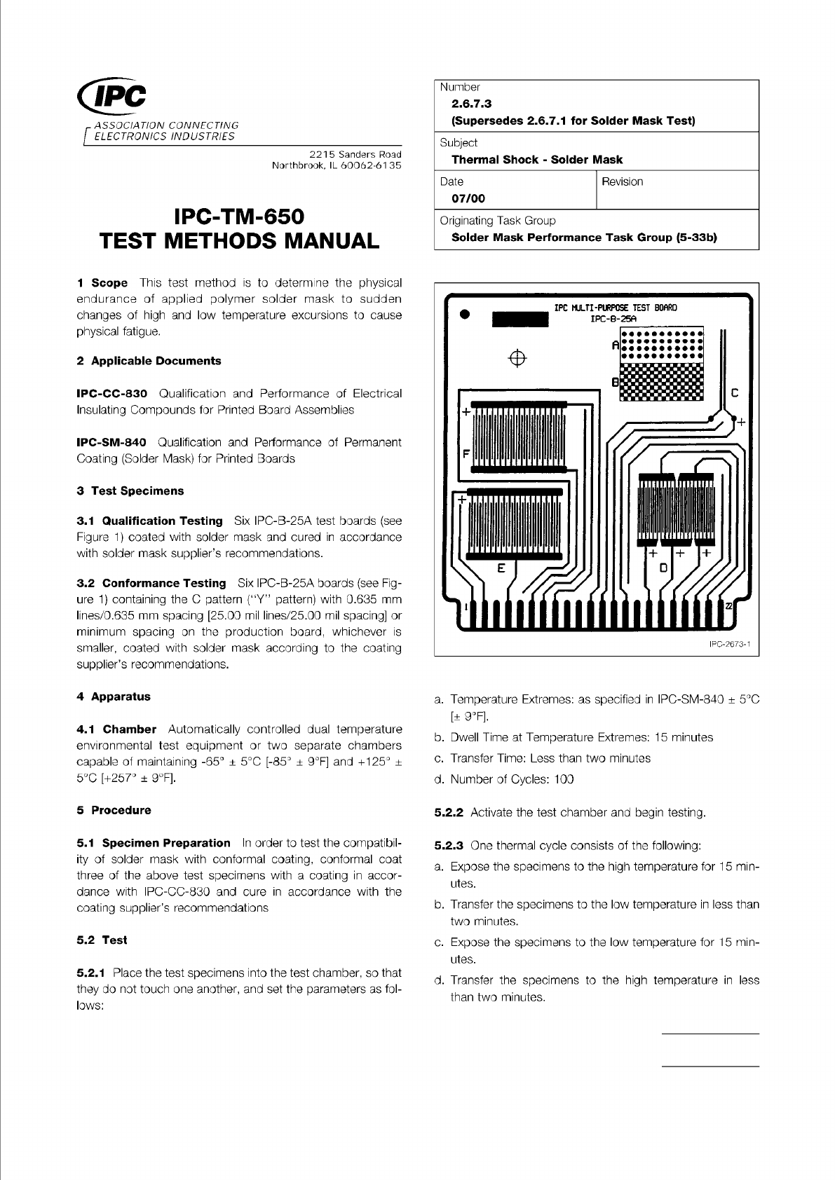
Figure 1 IPC-B-25A Test Board
Material in this Test Methods Manual was voluntarily established by Technical Committees of IPC. This material is advisory only
and its use or adaptation is entirely voluntary. IPC disclaims all liability of any kind as to the use, application, or adaptation of this
material. Users are also wholly responsible for protecting themselves against all claims or liabilities for patent infringement.
Equipment referenced is for the convenience of the user and does not imply endorsement by IPC.
Page 1 of 2
ASSOCIATION
CONNECTING
/
ELECTRONICS
INDUSTRIES
221
5
Sanders
Road
Northbrook,
IL
60062-61
35
IPC-TM-650
TEST
METHODS
MANUAL
1
Scope
This
test
method
is
to
determine
the
physical
endurance
of
applied
polymer
solder
mask
to
sudden
changes
of
high
and
low
temperature
excursions
to
cause
physical
fatigue.
2
Applicable
Documents
IPC-CC-830
Qualification
and
Performance
of
Electrical
Insulating
Compounds
for
Printed
Board
Assemblies
IPC-SM-840
Qualification
and
Performance
of
Permanent
Coating
(Solder
Mask)
for
Printed
Boards
3
Test
Specimens
3.1
Qualification
Testing
Six
IPC-B-25A
test
boards
(see
Figure
1)
coated
with
solder
mask
and
cured
in
accordance
with
solder
mask
supplier's
recommendations.
3.2
Conformance
Testing
Six
IPC-B-25A
boards
(see
Fig¬
ure
1)
containing
the
C
pattern
("Y”
pattern)
with
0.635
mm
lines/0.635
mm
spacing
[25.00
mil
lines/25.00
mil
spacing]
or
minimum
spacing
on
the
production
board,
whichever
is
smaller,
coated
with
solder
mask
according
to
the
coating
supplier's
recommendations.
4
Apparatus
4.1
Chamber
Automatically
controlled
dual
temperature
environmental
test
equipment
or
two
separate
chambers
capable
of
maintaining
-65°
±
5
℃
[-85°
+
9°F]
and
+125。
±
5
℃
[+257°
±
9°F].
5
Procedure
5.1
Specimen
Preparation
In
order
to
test
the
compatibil¬
ity
of
solder
mask
with
conformal
coating,
conformal
coat
three
of
the
above
test
specimens
with
a
coating
in
accor¬
dance
with
IPC-CC-830
and
cure
in
accordance
with
the
coating
supplier's
recommendations
5.2
Test
5.2.1
Place
the
test
specimens
into
the
test
chamber,
so
that
they
do
not
touch
one
another,
and
set
the
parameters
as
fol¬
lows:
Number
2.6.7.3
(Supersedes
2.6.7.
1
for
Solder
Mask
Test)
Subject
Thermal
Shock
-
Solder
Mask
Date
07/00
Revision
Originating
Task
Group
Solder
Mask
Performance
Task
Group
(5-33b)
a.
Temperature
Extremes:
as
specified
in
IPC-SM-840
±
5
℃
[±
9°F].
b.
Dwell
Time
at
Temperature
Extremes:
1
5
minutes
c.
Transfer
Time:
Less
than
two
minutes
d.
Number
of
Cycles:
100
5.2.2
Activate
the
test
chamber
and
begin
testing.
5.2.3
One
thermal
cycle
consists
of
the
following:
a.
Expose
the
specimens
to
the
high
temperature
for
15
min¬
utes.
b.
Transfer
the
specimens
to
the
low
temperature
in
less
than
two
minutes.
c.
Expose
the
specimens
to
the
low
temperature
for
15
min¬
utes.
d.
Transfer
the
specimens
to
the
high
temperature
in
less
than
two
minutes.
Note:
IPC-TM-650
Page 2 of 2
Number
2.6.7.3
Revision
Subject
Thermal
Shock
-
Solder
Mask
Date
07/00
5.2.4
Repeat
the
above
cycle
to
1
00
cycles
without
interrup¬
tion.
5.2.5
Remove
the
specimens
and
allow
them
to
reach
labo¬
ratory
conditions
as
specified
in
IPC-SM-840.
5.2.6
Evaluation
Examine
the
specimens,
on
both
sides,
for
all
visual
requirements
of
IPC-SM-840
using
10X
magnifi¬
cations
(Referee
of
30X
magnifications).
The
presence
of
cracks
in
solder
mask
is
not
a
suffi¬
cient
reason
for
rejection
unless
the
conformal
coating
has
also
cracked.
Report
findings
and
support
results
with
the
photographs,
if
appropriate.