IPC-TM-650 EN 2022 试验方法--.pdf - 第709页
IPC-TM-650 Number Subject Date Revision Page 3 of 4 2.6.9.2 Test to Determine Sensitivity of Electronic Components to Ultrasonic Energy 1/95 6.0 Notes Contact IPG for a list of test components. 6.1 References 6.1.1 Willi…
Tank Size
liters (gallons)
Power Density
watts/liter (watts/gallon)
Magnetostrictive Piezoelectric
19 (5) 66-76 (250-290) 33-38 (125-145)
38 (10) 53-68 (200-220) 26.5-29 (100-110)
95 and greater
(25 and greater)
21-32 (80-120) 10.5-16 (40-60)
It is important that the IPC receives as much data as
possible, whether it be to support previously submitted
data, add new data, or provide conflicting data for cer-
tain components. All information received will be
entered into a database for all IPC members to access.
The data will prove more useful as the volume of data
increases.
IPC-TM-650
Number
Subject Date
Revision
Page 2 of 4
2.6.9.2
Test
to
Determine
Sensitivity
of
Electronic
Components
to
Ultrasonic
Energy
1/95
4.1
Tank
Testing
shall
be
done
in
an
ultrasonic
tank,
pref¬
erably
in
the
equipment
to
be
used
in
production.
Water
is
to
be
used
as
the
ultrasonic
transmission
testing
fluid,
regardless
of
the
cleaning
agent
to
be
used
in
the
production
process.
Water
will
degas,
transmit
ultrasonics,
and
cavitate
more
eas¬
ily
than
most
new
cleaning
agents
and
is,
therefore,
consid¬
ered
a
"worst
case”
ultrasonic
testing
fluid.
Care
must
be
taken
to
maintain
water
level
during
testing.
Water
tempera¬
tures
should
be
maintained
at
60℃
±5℃
(1
40°F
±
10°F).
It
is
recommended
that
testing
equipment
operate
near
40Khz
or
higher
and
have
a
power
output
in
the
range
listed
in
the
chart
below.
Power
is
measured
as
the
output
from
the
gen¬
erator
to
the
transducers.
Note
in
the
chart
that
the
amount
of
power
necessary
is
scaled
for
various
tank
sizes.
/f
frequencies
other
than
40
KHz
range
or
power
densities
or
fre¬
quencies
differing
from
the
ranges
listed
above
are
to
be
used
in
production,
they
should
be
used
in
testing
as
well,
and
noted
on
the
Ultrasonic
Test
Data
Record.
4.2
Basket
Loose
components
will
be
placed
randomly
in
a
basket
or
in
a
beaker
(pyrex
or
stainless
steel)
for
testing.
If
a
basket
is
used,
it
should
be
made
of
stainless
steel
and
preferably
have
a
solid
bottom
for
optimal
ultrasonic
transmis¬
sion.
Tight
mesh
should
always
be
avoided.
If
a
beaker
is
chosen,
plastic
is
not
acceptable
as
it
will
dampen
ultrasonic
transmission.
5.1
Procedure
Note:
Standard
ESD
handling
methods
should
be
used
in
handling
and
assembly
so
as
not
to
have
ESD
damage
misin¬
terpreted
as
damage
by
ultrasonic
exposure.
5.1.1
Perform
functional
electrical
tests
on
components
to
be
subjected
to
ultrasonic
energy.
All
components
should
go
though
standard
prescreening
tests
to
eliminate
infant
mortal¬
ity.
Note
any
anomalies
and
ignore
any
malfunctions
in
further
testing.
degas.
Evidence
of
cavitation
should
be
obtained
by
placing
a
piece
of
aluminum
foil
in
the
water
for
one
minute
and
inspect¬
ing
for
an
erosion
pattern
(evidence
of
cavitational
activity).
If
the
surface
of
the
foil
is
not
disrupted,
continue
to
degas
until
the
foil
confirms
ultrasonic
activity.
Test
components
in
the
equipment
described
above.
Place
components
randomly
in
basket
or
in
a
beaker.
Baskets
should
be
suspended
off
the
bottom
of
the
tank
or
contain
stand
off
legs
to
keep
it
from
setting
directly
on
the
bottom
of
the
tank.
If
a
beaker
is
to
be
used,
it
should
be
filled
with
deionized
water
and
degassed
as
described
in
the
above
paragraph.
The
beaker
should
be
suspended
in
the
water-
filled
tank
and
not
placed
on
the
tank
bottom.
Subject
specimens
to
ultrasonics
for
a
time
period
1
0
times
longer
than
the
expected
exposure
anticipated
under
normal
cleaning
conditions
or
thirty
minutes,
whichever
is
longer.
5.1.3
(Optional)
Conduct
any
environmental
stressing
test(s)
as
specified
by
the
reliability
requirement
of
the
product
line
in
concern.
5.2
Evaluation
Method
5.2.1
Repeat
the
functional
electrical
test
in
5.1
.1
.
Any
fail¬
ures
should
be
analyzed
for
cause
of
failure.
Any
failure,
excluding
those
noted
in
5.1.1
or
attributable
to
a
docu¬
mented
defect
will
also
be
considered
caused
by
the
ultrason¬
ics.
5.2.2
Any
defect
which
is
not
assignable
to
a
previously
documented
defect
will
also
be
considered
caused
by
ultra¬
sonics.
5.2.3
Any
component
exhibiting
no
failures
or
1
00%
reliabil¬
ity
after
ultrasonic
testing
will
be
considered
safely
resistant
to
ultrasonics
under
the
conditions
tested.
Any
component
with
less
than
100%
reliability
will
be
suspect
unless
subsequent
testing
can
demonstrate
that
it
is
100%
reliable.
Unless
clas¬
sified
or
proprietary,
please
report
test
results
to
the
Ultrasonic
Energy
Task
Group
through
the
I
PC
for
compilation
in
the
attached
list.
5.1.2
Fill
the
test
tank
with
de-ionized
water.
Turn
on
ultra¬
sonics
and
allow
a
minimum
of
1
5
minutes
for
the
water
to
IPC-TM-650
Number
Subject Date
Revision
Page 3 of 4
2.6.9.2
Test
to
Determine
Sensitivity
of
Electronic
Components
to
Ultrasonic
Energy
1/95
6.0
Notes
Contact
IPG
for
a
list
of
test
components.
6.1
References
6.1.1
William
Vuono
and
Ayche
McClung,
"An
Update
on
an
Assessment
of
Ultrasonic
Cleaning
Techniques
for
Military
Printed
Wiring
Boards,”
presented
at
I
PC
Fall
Meeting,
1990.
6.1.2
B.P.
Richards,
P.
Burton
and
P.K.
Footner,
"Does
Ultrasonic
Cleaning
of
PCBs
Cause
Component
Problems;
An
Appraisal,"
I
PC
Technical
Review,
June
1990.
6.1.3
B.P.
Richards,
P.
Burton
and
P.K.
Footner,
"The
Effects
of
Ultrasonic
Cleaning
on
Device
Degradation,”
Circuit
World,
Vol.16,
No.
3.
6.1.4
B.P.
Richards,
P.
Burton
and
P.K.
Footner,
"The
Effects
of
Ultrasonic
Cleaning
on
Device
Degradation
-
An
Update,”
Circuit
World,
Vol.
17,
No.
4.
6.1.5
B.P.
Richards,
P.
Burton,
and
P.K.
Footner,
uThe
Effects
of
Ultrasonic
Cleaning
on
Device
Degradation
-
Quartz
Crystal
Devices,"
Circuit
World,
Vol.
18,
No.
4.
6.1.6
B.P.
Richards,
P.K.
Footner
and
P.
Burton,
“A
Study
of
the
Effect
of
Ultrasonic
Cleaning
on
Component
Quality
-
Hybrid
Devices,”
Circuit
World,
Vol.
19,
No.
1
.
6.1.7
Fritz
Ehorn,
11
Final
Report
on
the
Structural
Dynamic
Analysis
of
Selected
PWB
Components
under
the
400
Khz
Ultrasonic
Cleaning
Environment,"
MEL
Ref.
MS7507,
March
6,
1991.
6.1.8
William
Puskas
and
Gary
Ferrell,
"Process
Control
Ultrasonic
Cleaning,”
presented
at
Nepcon
West,
1988.
6.1.9
Kenneth
S.
Suslick,
"The
Chemical
Effects
of
Ultra¬
sound,
Scientific
American,
February,
1989.
6.1.10
Ismail
Kashkoush,
Ahmed
Busnaina,
Frederick
Kern,
Jr.
and
Robert
Kunesh,
*
4
Particle
Removal
Using
Ultrasonic
Cleaning,"
Institute
of
Environmental
Sciences,
1
990
Proceedings.
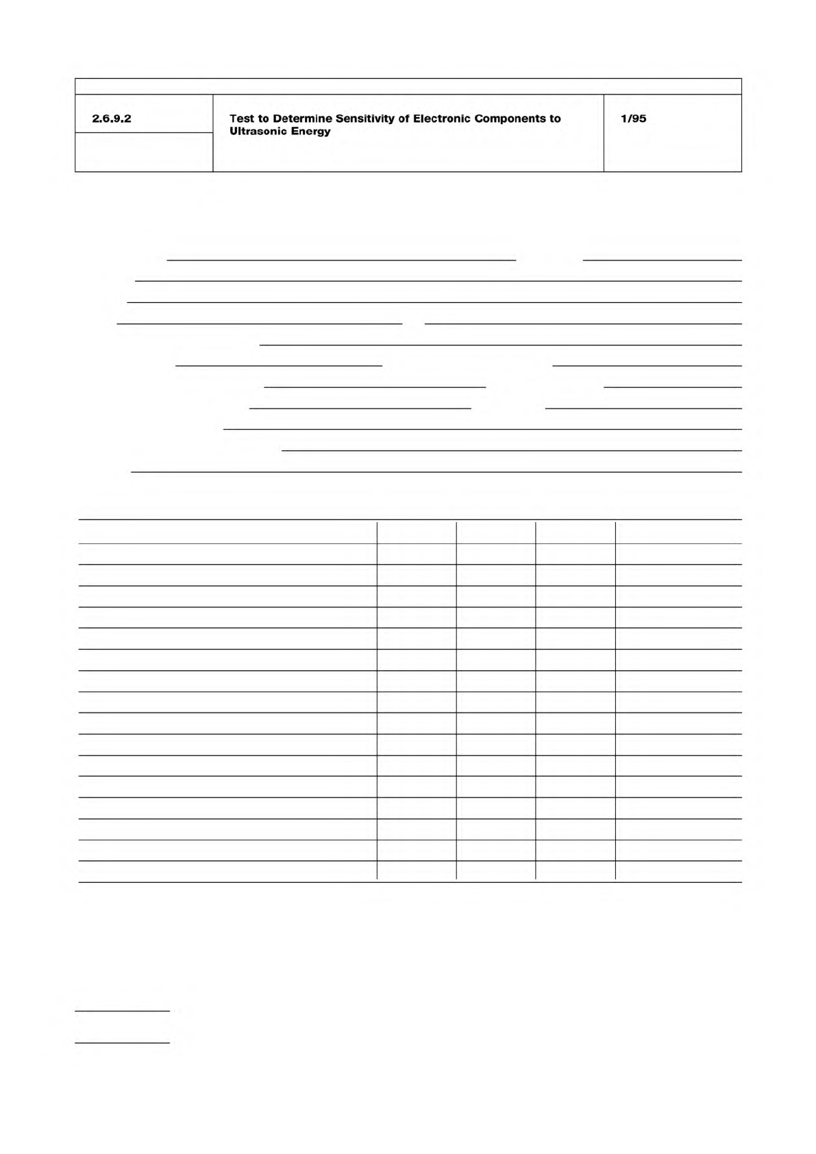
Ultrasonic Test Data Record
Name of tester Date
Company
Address
Phone Fax
Make and model of equipment
Tank size (liters) Dimensions (cm x cm x cm)
Generator output power (watts) Frequency (KHz)
No. of boards tested per trial Substrate
Exposure time (minutes)
Other stress testing (pre- or post-)
Describe
Component tested No. tested Passed Failed Comments
Type Mfgr Part #
Mail to: IPC Fax to: 847-509-9798
2215 Sanders Road
Northbrook, IL 60062-6135
Attn: Ultrasonic Cleaning Task Group
IPC-TM-650
Number
Subject Date
Revision
Page 4 of 4
2.6.9.2
Test
to
Determine
Sensitivity
of
Electronic
Components
to
Ultrasonic
Energy
1/95