IPC-TM-650 EN 2022 试验方法--.pdf - 第711页
MIL-STD-883 The Institute for Int erconnecting and Packaging E lectronic Circuits 2215 S anders Road • Northbrook, IL 60062-6135 Material in this T est M ethods Manual was vol untaril y establis hed by T echni cal Commit…
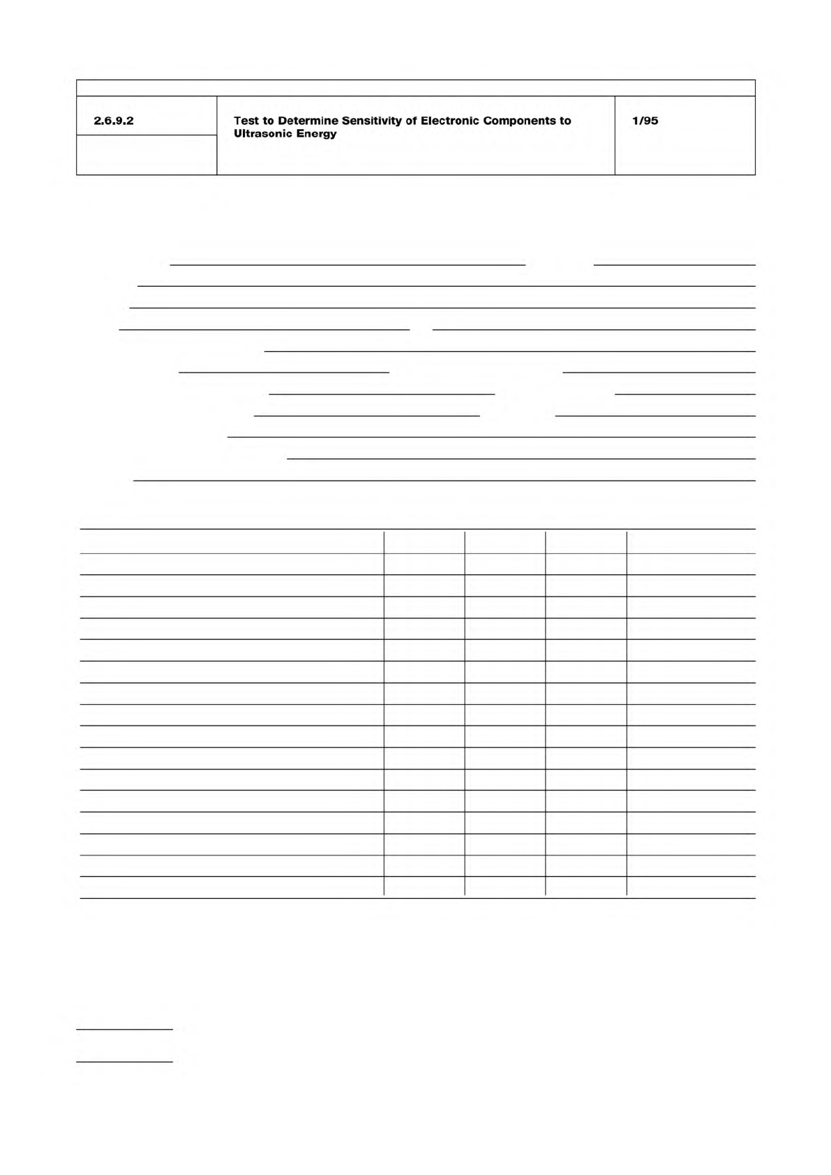
Ultrasonic Test Data Record
Name of tester Date
Company
Address
Phone Fax
Make and model of equipment
Tank size (liters) Dimensions (cm x cm x cm)
Generator output power (watts) Frequency (KHz)
No. of boards tested per trial Substrate
Exposure time (minutes)
Other stress testing (pre- or post-)
Describe
Component tested No. tested Passed Failed Comments
Type Mfgr Part #
Mail to: IPC Fax to: 847-509-9798
2215 Sanders Road
Northbrook, IL 60062-6135
Attn: Ultrasonic Cleaning Task Group
IPC-TM-650
Number
Subject Date
Revision
Page 4 of 4
2.6.9.2
Test
to
Determine
Sensitivity
of
Electronic
Components
to
Ultrasonic
Energy
1/95
MIL-STD-883
The Institute for Interconnecting and Packaging Electronic Circuits
2215 Sanders Road • Northbrook, IL 60062-6135
Material in this Test Methods Manual was voluntarily established by Technical Committees of the IPC. This material is advisory only
and its use or adaptation is entirely voluntary. IPC disclaims all liability of any kind as to the use, application, or adaptation of this
material. Users are also wholly responsible for protecting themselves against all claims or liabilities for patent infringement.
Equipment referenced is for the convenience of the user and does not imply endorsement by the IPC.
Page 1 of 2
IPC-TM-650
TEST
METHODS
MANUAL
1
.0
Scope
This
non-destructive
inspection
method
is
needed
to
ascertain
the
following
conditions:
a.
Innerlayer
shift
is
within
acceptable
tolerances.
b.
One
or
more
inner
layers
have
not
been
reversed.
c.
Drilled
holes
are
aligned
with
pads
to
the
extent
that
any
break-out
is
within
acceptable
tolerances.
d.
The
minimum
distance
between
a
drilled
hole
and
a
ground
plane
clearance
is
within
acceptable
tolerances.
The
test
method
will
entail
passing
X-rays
through
the
test
specimen
and
converting
the
transmitted
X-ray
image
into
a
visual
image
through
the
use
of
either
X-ray
film
or
a
flouro-
scopic
(real
time)
device.
Cautionary
notes:
The
construction
of
the
multilayer
with
respect
to;
number
of
layers,
thickness
of
copper
and
presence
other
metals
such
as
heat
sinks
(e.g.
Invar),
will
determine
the
power
and
sensi¬
tivity
of
the
X-ray
apparatus
which
can
be
used.
All
X-ray
apparatus
should
be
registered
with
the
appropriate
state
or
regional
Radiation
Control
agency.
A
radiation
safety
program
should
be
implemented.
2
.0
Applicable
Documents
Method
2012.5,
Radiography
3
.0
Test
Specimen
The
Test
specimen
shall
be
a
multi¬
layer
printed
wiring
board
having
a
maximum
size
of
20
x
24
inches.
4
.0
Apparatus
or
Material
(Ref.
MIL-STD-883C).
The
apparatus
and
materials
for
this
test
shall
include:
4.1
A
radiographic
(X-ray)
source
for
generating
X-rays
of
sufficient
voltage
and
power
to
penetrate
the
test
specimen.
The
focal
distance
and
focal
spot
size
of
the
source
shall
be
adequate
to
produce
a
well
defined
image
of
a
0.001
inch
copper
wire.
4.2
If
film
is
the
imaging
medium
The
film
used
is
to
be
a
fine
grain
single
emulsion
X-ray
film
with
resolution
capable
of
resolving
a
0.001
copper
wire
and
fray
scale
capable
of
detecting
the
shift
of
a
single
layer.
Number
2.6.10
Subject
X-Ray
(Radiography),
Multilayer
Printed
Wiring
Printed
Board
Test
Methods
Date
Revision
8/97
A
Originating
Task
Group
Board
T・M・
Task
Group,
7-1
Id
4.3
Film
holder
A
lead
backed
film
holder
to
prevent
back
scatter
of
radiation.
4.4
Radiographic
Viewer
Capable
of
0.001
inches
resolu¬
tion.
4.5
Radiographic
quality
standards
Suitable
Image
Qual¬
ity
Indicator
capable
of
verifying
the
ability
to
detect
all
speci¬
fied
defects.
4.6
Film
processing
means
Manual
tray
development
or
a
film
processor
is
to
be
used.
If
the
film
processor
has
a
glove
box
and
suitable
film
holders,
a
dark
room
is
not
required.
If
manual
tray
development
is
used,
a
dark
room
is
required.
4.7
Silver
film
densitometer
Capable
of
measuring
silver
film
density
up
to
3.0.
4.8
If
a
fluoroscopic
(real
time)
X-ray
inspection
system
is
used,
the
X-ray
image
detecting
device
or
x-ray
camera
should
be
capable
of
resolving
a
0.001
copper
wire
and
a
gray
scale
capable
of
detecting
the
shift
of
a
single
layer
of
the
specimen.
4.8.1
A
means
is
to
be
provided
for
recording
or
making
a
hard
copy
of
the
fluoroscopic
(real
time)
X-ray
image.
4.9
Image
Identification
Each
radiographic
image
(film
or
real
time)
shall
be
identified
with
the
following
information:
•
Manufacturer's
name
•
Part
number
•
Serial
number
(when
applicable)
•
Date
code
(if
marked
on
specimen)
•
View
number
•
Reference
code
for
x-ray
procedures
used.
5.0
Procedure
5.1
Preparation
Alignment
of
the
X-ray
beam
center
line,
specimen
inspection
area
and
image
detector
field
of
view
must
be
insured
so
that
parallax
distortion
does
not
adversely
effect
the
interpretation
of
the
result.
(See
reference)
txTran A.
3 millgrams
IPC-TM-650
Number
Subject Date
Revision
Page 2 of 2
2.6.10
X-Ray
(Radiography),
Multilayer
Printed
Wiring
Printed
Board
Test
Methods
8/97
A
Parallax
displacement
distortion
will
be
indicated
when
round
holes
appear
oval
or
"cats
eyed"
on
the
X-ray
image.
For
a
hole
drilled
through
a
panel
of
thickness,
t,
and
offset
from
the
center
of
the
X-ray
beam
axis
by
the
angle
A,
the
parallax
dis¬
placement
between
the
top
and
bottom
of
the
hole
will
be
equal
to
5.2
Radiographic
Quality
Standard
A
radiographic
qual¬
ity
standard
such
as
an
ASTM
Image
Quality
Indicator
or
other
agreeable
indicator
shall
be
used
on
all
radiographic
studies.
5.3
Exposure
when
film
is
used
The
necessary
X-ray
penetration
exposure
will
depend
on
the
construction
of
the
multilayer,
X-ray
source
anode
voltage,
the
anode
current,
the
distance
from
the
source
to
the
film
plane
and
the
speed
or
sensitivity
of
the
film.
The
exposure
should
be
sufficient
to
produce
an
optical
density
of
at
least
2.0
at
those
portions
of
the
film
receiving
the
highest
X-ray
exposure,
such
as,
holes
or
unattenuated
areas.
In
addition
the
conditions
of
paragraph
1
.0
with
respect
to
resolution
and
gray
scale
must
be
met.
The
exposure
apparatus
for
film
can
consist
of
an
industrial
shielded
X-ray
cabinet
with
a
nominal
anode
voltage
of
80
kilovolts,
nominal
anode
current
of
and
a
focal
spot
to
film
distance
adequate
to
avoid
parallax
distortion
of
the
X-ray
film
image.
5.4
Exposure
for
realtime
systems
The
X-ray
source
operating
parameters
must
be
matched
to
the
X-ray
camera
sensitivity
of
the
system
to
produce
an
X-ray
image
of
suffi¬
cient
quality
to
comply
with
the
conditions
of
paragraph
1
.0.
6.0
Notes
None