IPC-TM-650 EN 2022 试验方法--.pdf - 第728页
IPC-A-600 IPC-MI-660 Note: The Institute for Int erconnecting and Packaging E lectronic Circuits 2215 S anders Road • Northbrook, IL 60062-6135 Material in this T est M ethods Manual was vol untaril y establis hed by T e…
minor
major
IPC-TM-650
Page 3 of 3
Number
2.6.15
Subject
Corrosion,
Flux
Date
06/04
Revision
C
held
for
30
minutes.
The
humidity
should
then
be
increased
to
93%RH.
5.6.3.3
Expose
specimen
to
the
above
environment
for
240
hours
(10
days).
M
and
H
fluxes
may
be
tested
in
the
cleaned,
as
well
as
uncleaned,
condition.
Specimens
shall
be
cleaned
per
the
manufacturers
instructions.
5.7
Evaluation
5.7.1
After
the
exposure
period,
remove
test
specimens
from
humidity
chamber,
examine
at
20X
magnification
and
compare
with
observations
noted
in
6.5
(see
8.2).
5.7.2
For
purposes
of
this
test
method,
the
following
defini¬
tion
of
corrosion
shall
prevail:
"A
chemical
reaction
between
the
copper,
the
solder,
and
the
constituents
of
the
flux
resi¬
dues,
which
occurs
after
soldering
and
during
exposure
to
the
above
environmental
conditions.*
*
Corrosion
for
this
test
is
classified
as
follows:
5.7.2.1
Minor
Corrosion
Any
initial
change
of
color,
which
may
develop
when
the
test
panel
is
heated
during
soldering,
is
disregarded.
Discrete
white
or
colored
spots
in
the
flux
resi¬
dues
or
a
color
change
to
green-blue
without
pitting
of
the
copper
or
formation
of
excrescences
is
regarded
as
corrosion.
5.7.2.2
Major
Corrosion
Any
initial
change
of
color
which
may
develop
when
the
test
panel
is
heated
during
soldering
is
disregarded.
Subsequent
development
of
green-blue
discol¬
oration
with
observation
of
pitting
of
the
copper
panel
or
excrescences
at
the
interfaces
of
the
flux
residue
and
copper
boundary,
is
regarded
as
corrosion.
6
Notes
6・1
Questionable
results
may
be
confirmed
by
analyzing
the
suspected
corrosion
via
Energy
Dispersive
X-ray
Spectros¬
copy
(EDS)
for
the
presence
of
copper.
6.2
Color
photos
before
and
after
the
test
are
valuable
tools
in
identifying
and
documenting
corrosion.
6.3
Safety
Observe
all
appropriate
precautions
on
MSDS
for
chemicals
involved
in
this
test
method.
IPC-A-600
IPC-MI-660
Note:
The Institute for Interconnecting and Packaging Electronic Circuits
2215 Sanders Road • Northbrook, IL 60062-6135
Material in this Test Methods Manual was voluntarily established by Technical Committees of the IPC. This material is advisory only
and its use or adaptation is entirely voluntary. IPC disclaims all liability of any kind as to the use, application, or adaptation of this
material. Users are also wholly responsible for protecting themselves against all claims or liabilities for patent infringement.
Equipment referenced is for the convenience of the user and does not imply endorsement by the IPC.
Page 1 of 3
IPC-TM-650
TEST
METHODS
MANUAL
1
.0
Scope
This
procedure
is
a
rapid
means
for
evaluating
glass
epoxy
laminate
integrity
on
different
lots
of
base
lami¬
nate
materials
before
placing
materials
on
the
production
floor,
and
thereby
reducing
the
cost
of
processing
material
which
may
later
prove
to
be
defective.
2
.0
Applicable
Documents
Acceptability
of
Printed
Boards
Guidelines
for
Incoming
Inspection
of
Raw
Mate¬
rials
3
.0
Specimens
The
samples
of
qualification
or
incoming
production
test
coupons
shall
be
4.0
inch
x
4.0
inch
x
1/16
inch
thick
(see
7.1)
and
etched
using
the
standard
commer¬
cial
practices
procedure
of
the
individual
test
facility.
The
test
coupons
can
be
taken
from
any
part
of
the
laminate.
The
test
strip
may
be
sheared,
but
the
individual
test
coupons
shall
be
sawed
and
their
edges
sanded.
4
.0
Number
of
Test
Coupons
to
be
Tested
Five
coupons
shall
be
tested
and
may
arbitrarily
contain
a
known
“pass”
and
"fail''
control
coupon.
However,
if
a
failure
mode
is
estab¬
lished,
a
second
set
of
5
samples
shall
be
tested
from
another
laminate
and
this
set
must
contain
a
pass
and
fail
control.
The
number
of
test
coupons
tested
at
any
one
time
should
be
lim¬
ited
to
the
capacity
of
the
pressure
vessel
being
used.
5
.0
Apparatus
5.1
Any
standard
laboratory
autoclave
pressure
vessel
hav¬
ing
a
6-quart
capacity.
A
commercial
household
6-quart
stain¬
less
steel
pressure
cooker
capable
of
developing
1
5
psi
pres¬
sure
(the
1
5
psi
pressure
set
at
the
location
of
the
test)
may
be
used
if
equipped
with
a
properly
calibrated
pressure
gauge
to
maintain
15
psi
±
0.5
psi
pressure.
5.2
A
laboratory
solder
pot
capable
of
maintaining
a
solder
bath
(SN
60)
at
500°F
-0°
+
10°F.
5.3
Stop
watch.
5.4
Solder
pot
containing
SN
60/40
solder.
6
.0
Test
Number
2.6.16
Subject
Pressure
Vessel
Method
for
Glass
Epoxy
Laminate
Integrity
Date
Revision
7/85
Originating
Task
Group
N/A
6.1
Preparation
6.1.1
Cut
test
coupons
only
by
sawing,
and
sand
the
edges
of
the
specimens
so
they
are
smooth.
6.1.2
Etch
specimens
to
remove
metal
foil
except
in
any
areas
which
may
have
identification
codes.
6.1.3
Apply
permanent
identification
markings
on
speci¬
mens
on
the
end
that
will
not
be
immersed
in
the
solder
pot.
6.1.4
The
specimens
will
be
placed
in
a
suitable
rack
for
suspending
in
the
pressure
vessel.
The
specimens
should
not
be
drilled
for
suspension
as
this
creates
a
path
for
moisture
incursion,
giving
false
results.
6.1.5
Pour
water
into
pressure
vessel
to
approximately
1
.0
inch
depth.
Cover
and
bring
to
a
boil
without
pressurizing.
6.2
Test
6.2.1
When
steam
is
observed
at
the
vent,
uncover
and
suspend
specimens
vertically
over
boiling
water,
being
careful
not
to
allow
specimens
to
touch
each
other
or
the
walls
of
the
pressure
vessel.
This
step
must
be
done
rapidly
to
avoid
undue
cooling
of
the
water
and
pressure
vessel.
6.2.2
The
heat-up
time
should
be
controlled
at
7
minutes
±
1
minute.
6.2.3
After
reaching
15
psi.
maintain
this
condition
for
30
minutes
+
2-0
minutes.
Other
pressure
vessel
dwell
times
may
be
agreed
upon
between
user
and
vendor.
6.2.4
At
the
end
of
the
exposure
time,
cool
and
vent
the
pressure
vessel
as
recommended
by
the
manufacturer.
6.2.5
Carefully
remove
the
hot
specimens
from
the
pressure
vessel
and
blot
dry
with
paper
towel
(see
caution
notes).
6.2.6
The
specimens
shall
be
maintained
at
ambient
tem¬
perature,
and
within
10
minutes
it
shall
be
immersed
vertically
(with
the
edge
parallel
to
the
solder
surface)
into
the
solder
bath
which
is
maintained
at
either
500°F
-0
+
10°F
for
20
Note:
Value Condition
CONDITION 1
CONDITION 2
IPC-TM-650
Number
Subject Date
Revision
Page 2 of 3
2.6.16
Pressure
Vessel
Method
for
Glass
Epoxy
Laminate
Integrity
7/85
seconds.
Immersion
and
withdrawal
rates
should
not
exceed
2
seconds.
Do
not
allow
test
coupons
to
touch
bottom
of
sol¬
der
bath.
Other
solder
bath
temperatures
maybe
agreed
upon
by
user
and
vendor.
6.3
Evaluation
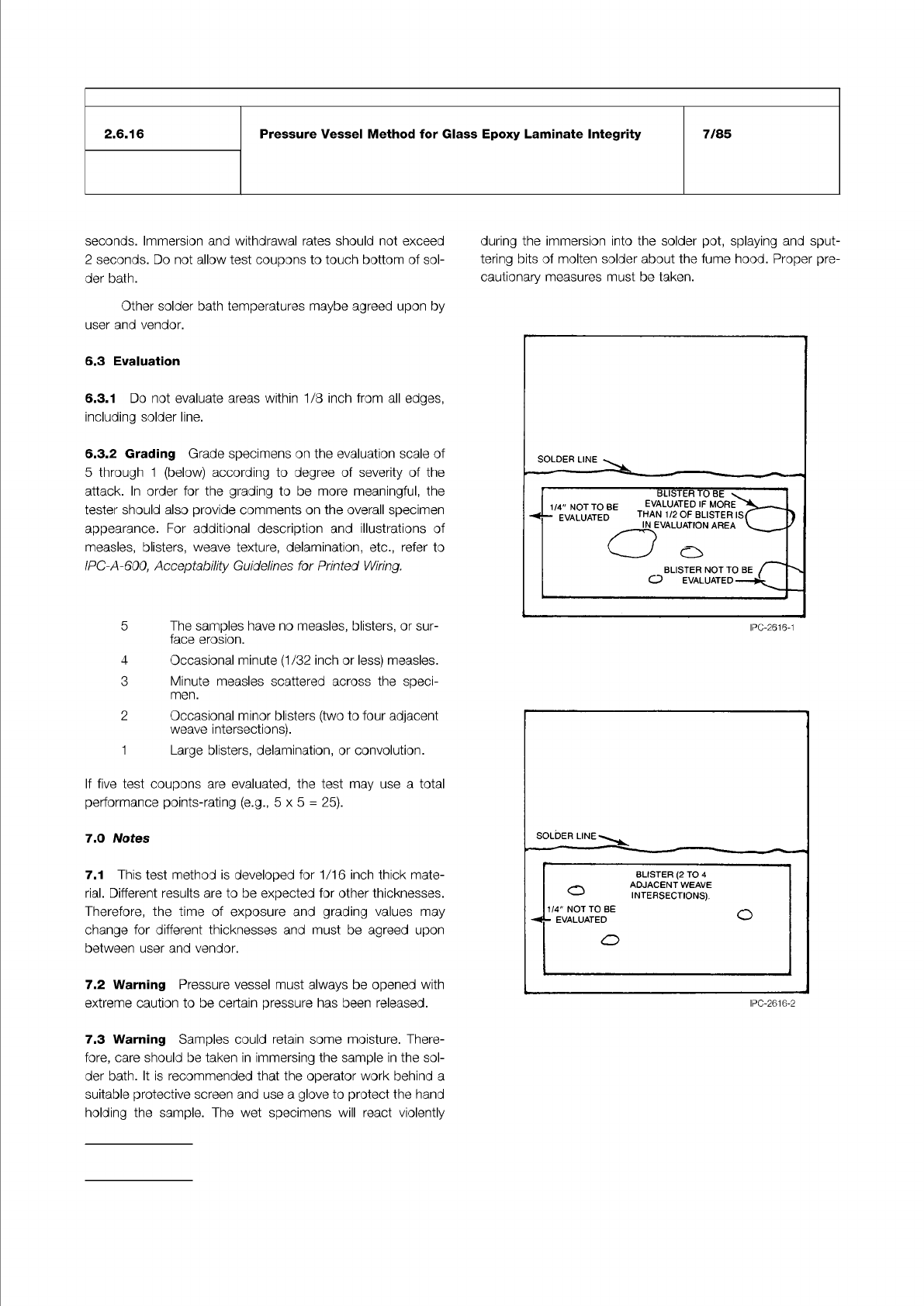
6.3.1
Do
not
evaluate
areas
within
1/8
inch
from
all
edges,
including
solder
line.
6.3.2
Grading
Grade
specimens
on
the
evaluation
scale
of
5
through
1
(below)
according
to
degree
of
severity
of
the
attack.
In
order
for
the
grading
to
be
more
meaningful,
the
tester
should
also
provide
comments
on
the
overall
specimen
appearance.
For
additional
description
and
illustrations
of
measles,
blisters,
weave
texture,
delamination,
etc.,
refer
to
IPC-A-600,
Acceptability
Guidelines
for
Printed
Wiring.
5
The
samples
have
no
measles,
blisters,
or
sur¬
face
erosion.
4
Occasional
minute
(1/32
inch
or
less)
measles.
3
Minute
measles
scattered
across
the
speci¬
men.
2
Occasional
minor
blisters
(two
to
four
adjacent
weave
intersections).
1
Large
blisters,
delamination,
or
convolution.
If
five
test
coupons
are
evaluated,
the
test
may
use
a
total
performance
points-rating
(e.g.,
5x5
=
25).
7.0
Notes
7.1
This
test
method
is
developed
for
1/16
inch
thick
mate¬
rial.
Different
results
are
to
be
expected
for
other
thicknesses.
Therefore,
the
time
of
exposure
and
grading
values
may
change
for
different
thicknesses
and
must
be
agreed
upon
between
user
and
vendor.
7.2
Warning
Pressure
vessel
must
always
be
opened
with
extreme
caution
to
be
certain
pressure
has
been
released.
7.3
Warning
Samples
could
retain
some
moisture.
There¬
fore,
care
should
be
taken
in
immersing
the
sample
in
the
sol¬
der
bath.
It
is
recommended
that
the
operator
work
behind
a
suitable
protective
screen
and
use
a
glove
to
protect
the
hand
holding
the
sample.
The
wet
specimens
will
react
violently
during
the
immersion
into
the
solder
pot,
splaying
and
sput¬
tering
bits
of
molten
solder
about
the
fume
hood.
Proper
pre¬
cautionary
measures
must
be
taken.
SOLDER
LINE
IPC-2616-1
SOLDER
LINE
BLISTER
(2
TO
4
—
-
ADJACENT
WEAVE
J
INTERSECTIONS).
1/4"
NOT
TO
BE
-
EVALUATED
o
o
IPC-2616-2