IPC-TM-650 EN 2022 试验方法--.pdf - 第782页
NOTE: Material in this T est Methods Manual was voluntarily established by T echnical Committees of the IPC. Thi s mate rial is ad visory o nly and its use or adaptation is entirely voluntary . IPC disclaims all lia bili…
NOTE:
Material in this Test Methods Manual was voluntarily established by Technical Committees of the IPC. This material is advisory only
and its use or adaptation is entirely voluntary. IPC disclaims all liability of any kind as to the use, application, or adaptation of this
material. Users are also wholly responsible for protecting themselves against all claims or liabilities for patent infringement.
Equipment referenced is for the convenience of the user and does not imply endorsement by the IPC.
Page 1 of 1
ASSOCIATION
CONNECTING
/
ELECTRONICS
INDUSTRIES
221
5
Sanders
Road
Northbrook,
IL
60062-61
35
IPC-TM-650
TEST
METHODS
MANUAL
1
.0
Scope
1.1
To
determine
the
mechanical
strength
of
the
crimped
contact
-to-conductor
joint.
2
.0
Reference
Documents
2.1
Information
in
this
section
is
intended
to
parallel
the
test
method
described
in
EIA-RS-364/TP-08.
3
.0
Test
Specimen
3.1
A
contact
and
conductor
crimped
together
with
the
specified
tool.
A
contact
may
be
crimped
to
both
ends
of
the
con¬
ductor
to
facilitate
fixturing.
4
.0
Apparatus
4.1
Clamps,
jaws,
or
other
means
to
hold
the
contact
and
conductor.
4.2
A
force
measuring
device
capable
of
measuring
the
specified
forces
at
a
rate
of
travel
of
1
±
1/4
inch
per
minute.
Number
3.3
Subject
Crimp
Tensil
Strength,
Connectors
Date
Revision
7/75
A
Originating
Task
Group
N/A
5
.0
Procedure
5
J
The
sample
shall
be
mounted
in
the
tensile
tester
and
an
axial
force
sufficient
to
rupture
the
contact-to-conductor
crimp
shall
be
applied.
The
peak
force
required
to
separate
the
con¬
tact
from
the
conductor
shall
be
recorded
and
shall
not
be
less
than
the
minimum
specified
crimp
tensile
strength
as
defined
in
the
individual
contact
or
connector
specification
for
the
particular
wire
size
under
test.
5.2
The
tested
sample
shall
be
visually
examined
for
distor¬
tion
of
the
crimp
barrel
or
area
to
the
extent
that
it
is
unfit
for
further
use.
The
condition
of
crimp
failure
shall
be
noted
as
one
of
the
following:
1.
Slip
(pull-out)
2.
Conductor
broken
within
crimp
area
or
immediately
adja¬
cent
to
the
crimp
area
(including
any
strain
relief).
6.
0
Notes
6.1
Acceptance
criteria
shall
be
established
as
the
minimum
acceptable
mechanical
strength
of
the
crimped
connection
as
defined
by
the
individual
contact
or
connector
specification.
NOTE:
Material in this Test Methods Manual was voluntarily established by Technical Committees of the IPC. This material is advisory only
and its use or adaptation is entirely voluntary. IPC disclaims all liability of any kind as to the use, application, or adaptation of this
material. Users are also wholly responsible for protecting themselves against all claims or liabilities for patent infringement.
Equipment referenced is for the convenience of the user and does not imply endorsement by the IPC.
Page 1 of 2
r
ASSOCIATION
CONNECTING
/
ELECTRONICS
INDUSTRIES
2215
Sanders
Road
Northbrook,
IL
60062-6135
IPC-TM-650
TEST
METHODS
MANUAL
1
.0
Scope
1.1
To
determine
the
effects
of
subjecting
connectors
to
mating
and
unmating
cycles
simulating
the
expected
life.
2
.0
Reference
Documents
2.1
Information
in
this
section
is
intended
to
parallel
the
test
method
described
in
EIA-RS-364/TP-09.
3
.0
Test
Specimen
3.1
One
piece
connector
3.1.1
A
connector
(plug
and
receptacle)
complete
with
all
applicable
guide,
keying
and
engaging
hardware
or
a
card
edge
receptacle.
3.2
Two
piece
connector
3.2.1
A
connector
(header
and
receptacle
or
plug
and
receptacle)
complete
with
all
applicable
guide,
keying
and
engaging
hardware
and
appropriate
flat
cable.
3.3
Unless
otherwise
specified
in
the
individual
connector
specification,
the
test
samples
(or
engaging
hardware)
shall
not
be
lubricated
or
otherwise
coated
prior
to
test.
4
.0
Apparatus
4.1
One
piece
connector.
4.1.1
Test
blade
as
shown
in
Figure
1
to
simulate
a
mating
printed
wiring
board
of
maximum
thickness
for
card
edge
(one
piece)
connector.
4.2
Two
piece
connector.
4.2.1
The
mating
connector
shall
be
used
to
test
for
dura¬
bility
of
two
piece
connectors.
4.3
Clamps,
jaws,
or
other
means
to
hold
the
receptacle
and
plug
or
test
blade.
Number
3.4
Subject
Durability,
Connectors
Date
Revision
1/83
B
Originating
Task
Group
N/A
While
manual
cycling
of
the
connectors
is
permitted,
proper
alignment
and
orientation
is
most
readily
maintained
in
a
mechanical
device
specifically
designed
for
this
test.
5
.0
Procedure
5.1
The
sample
shall
be
mounted
in
the
tester,
carefully
aligned
and
fully
mated
and
unmated
for
the
number
of
cycles
specified
in
the
individual
connector
specification.
5.2
Unless
otherwise
specified
in
the
individual
connector
specification,
the
cycling
rate
shall
be
200
to
600
cycles
per
hour
and
no
electrical
load
shall
be
applied
to
the
samples
during
the
test.
5.3
At
the
intervals
specified
in
the
individual
connector
specification,
inspections
or
tests
may
be
performed.
5.4
After
completion
of
the
specified
number
of
cycles,
the
sample
shall
be
visually
examined
for
evidence
of
the
follow¬
ing
which
may
be
excessive
or
detrimental
to
the
function
of
the
connector.
A.
Wear
on
engaging
hardware.
B.
Uneven
wear,
galling,
or
removal
of
plating
on
contacts,
guide
hardware,
etc.
C.
Free
metal
chips
in
the
contact
area.
D.
Displaced,
bent,
or
broken
contacts.
E.
Pierced
resilient
inserts
or
broken
or
chipped
hard
dielec¬
trics.
6.0
Notes
6.1
Acceptance
criteria
shall
be
established
in
terms
of
one,
or
any
combination
of
the
following:
(See
5.3)
A.
The
maximum
allowable
total
mating
force
during
the
test.
B.
The
minimum
individual
contact
separation
force
during
or
after
the
test.
C.
The
maximum
allowable
change
in
contact
resistance
after
the
test.
D.
The
degree
and
criticality
of
wear
and/or
component
dam¬
age
resulting
from
the
test.
4.4
Automatic
or
semi-automatic
tester
to
mate
and
unmate
the
connector
at
the
specified
rate.
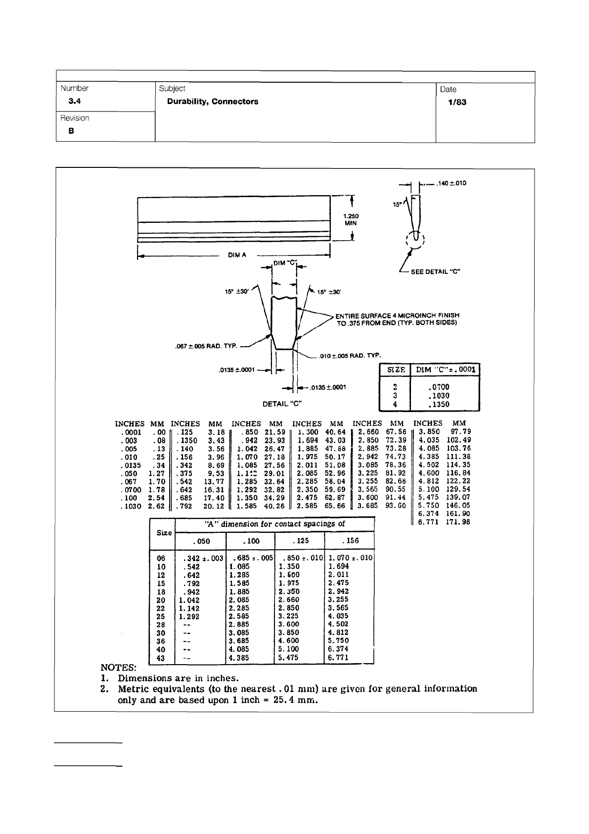
Figure 1 One Piece Edge Connector Mechanical Gages
IPC-TM-650
Page 2 of 2
Number
3.4
Subject
Durability,
Connectors
Date
1/83
Revision
B
.140
±.010
1.250
DIMA
DETAIL
"C*
15°
±30*
.067
±.005
RAD.
TYP.
.010
+.005
RAD.
TYP.
.0135
+.0001
35
+
0001
DETAIL
-C"
ENTIRE
SURFACE
4
MICROINCH
FINISH
TO
.375
FROM
END
(TYP.
BOTH
SIDES)
卜
SIZE
DIM
"C-'t.OOOl
2
.0700
3
.1030
4
.1350
INCHES
MM
INCHES
MM
INCHES
MM
INCHES
MM
INCHES
MM
.0001
.
00
.
125
3.18
.850
21.59
1.300
40.64
I
2.660
67.56
.003
.08
.
1350
3.43
.942
23.93
1.694
43.03
2.850
72.39
.005
.
13
.
140
3.56
1.042
26.
47
1.885
47.88
2.885
73.28
.010
.25
.156
3.96
1.070
27.
18
1.975
50.17
2.942
74.73
.0135
.34
.342
8.69
1.085
27.56
2.011
51.08
3.085
78.36
.050
1.27
.375
9.53
1.112
29.01
2.085
52.96
3.225
81.92
.067
1.70
.542
13.77
1.285
32.64
2.285
58.04
3.255
82.68
.0700
1.78
.642
16.31
1.292
32.82
2.350
59.
69
3.565
90.55
.
100
2.54
.685
17.40
1.350
34.29
2.475
62.87
3.600
91.44
.
1030
2.
62
.792
20.
12
1.585
40.26
2.585
65.66
3.685
93.60
Size
"A”
dimension
for
contact
spacings
of
.050
.100
.125
.156
06
.342
±.003
.685
s.
005
.850
±.010
1.070
±.010
10
.542
1.085
1.350
1.694
12
•
642
1.285
1.
600
2.011
15
.792
1.585
1.
975
2.475
18
.942
1.885
2.350
2.942
20
1.042
2.085
2.660
3.255
22
1.142
2.285
2.850
3.565
25
1.292
2.585
3.225
4.
035
28
2.885
3.600
4.502
30
3.085
3.850
4.812
36
3.685
4.600
5.750
40
4.085
5.
100
6.374
43
—
4.385
5.475
6.
771
」
INCHES
MM
3.850
97.79
4,035
102.49
4,085
103.76
4.385
111.38
4.502
114.35
4.600
116.84
4.812
122.22
5.
100
129.54
5.475
139.
07
5.750
146.05
6.374
161.90
6.771
171.98
1.
Dimensions
are
in
inches.
2.
Metric
equivalents
(to
the
nearest
.
01
mm)
are
given
for
general
infoi'mation
only
and
are
based
upon
1
inch
=
25.4
mm.