IPC-TM-650 EN 2022 试验方法--.pdf - 第784页
Steady State T est Humidity—T emperature C ycling T est Material in this T est Methods Manual was voluntarily established by T echnical Committees of the IPC. Thi s mate rial is ad visory o nly and its use or adaptation …
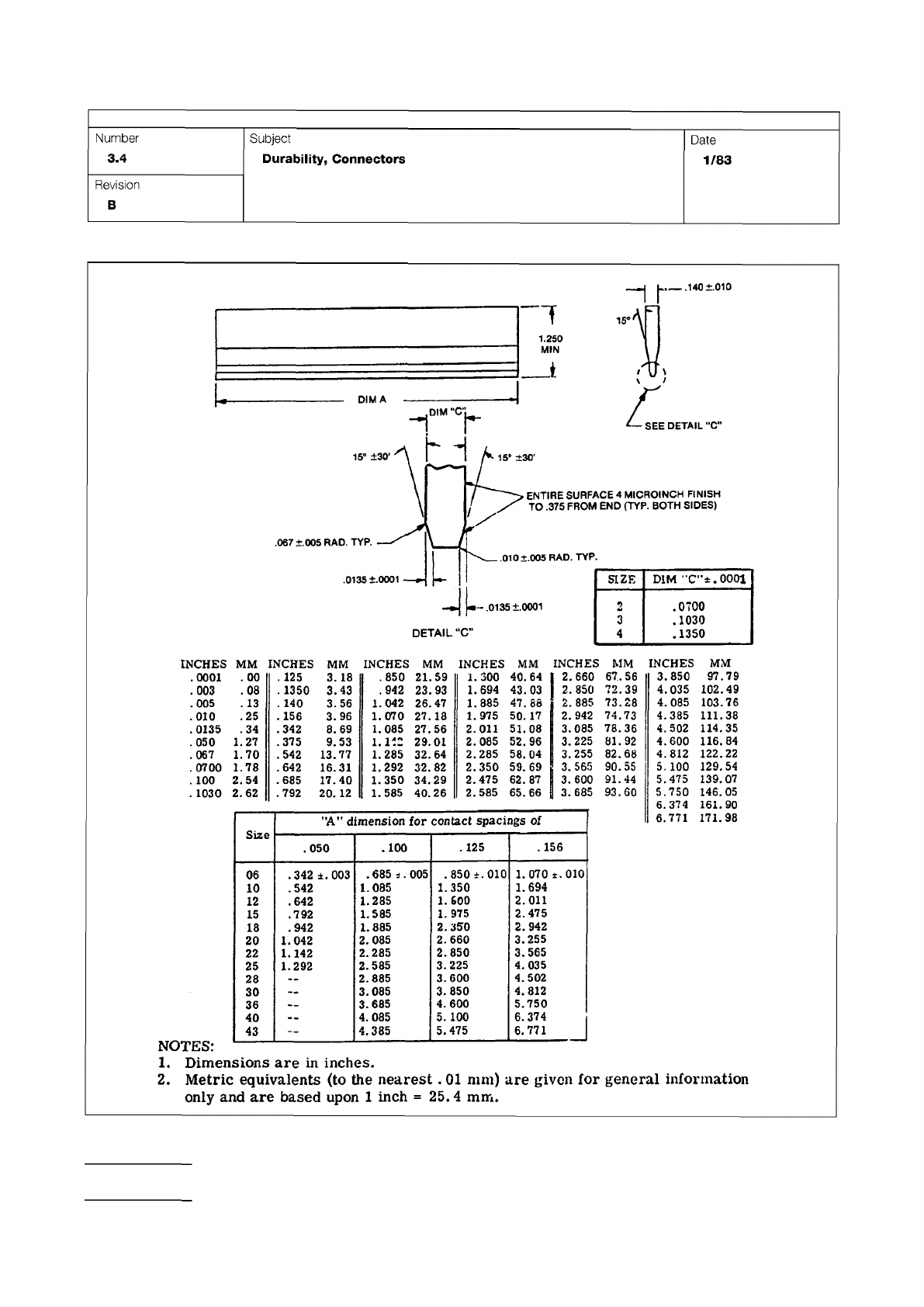
Figure 1 One Piece Edge Connector Mechanical Gages
IPC-TM-650
Page 2 of 2
Number
3.4
Subject
Durability,
Connectors
Date
1/83
Revision
B
.140
±.010
1.250
DIMA
DETAIL
"C*
15°
±30*
.067
±.005
RAD.
TYP.
.010
+.005
RAD.
TYP.
.0135
+.0001
35
+
0001
DETAIL
-C"
ENTIRE
SURFACE
4
MICROINCH
FINISH
TO
.375
FROM
END
(TYP.
BOTH
SIDES)
卜
SIZE
DIM
"C-'t.OOOl
2
.0700
3
.1030
4
.1350
INCHES
MM
INCHES
MM
INCHES
MM
INCHES
MM
INCHES
MM
.0001
.
00
.
125
3.18
.850
21.59
1.300
40.64
I
2.660
67.56
.003
.08
.
1350
3.43
.942
23.93
1.694
43.03
2.850
72.39
.005
.
13
.
140
3.56
1.042
26.
47
1.885
47.88
2.885
73.28
.010
.25
.156
3.96
1.070
27.
18
1.975
50.17
2.942
74.73
.0135
.34
.342
8.69
1.085
27.56
2.011
51.08
3.085
78.36
.050
1.27
.375
9.53
1.112
29.01
2.085
52.96
3.225
81.92
.067
1.70
.542
13.77
1.285
32.64
2.285
58.04
3.255
82.68
.0700
1.78
.642
16.31
1.292
32.82
2.350
59.
69
3.565
90.55
.
100
2.54
.685
17.40
1.350
34.29
2.475
62.87
3.600
91.44
.
1030
2.
62
.792
20.
12
1.585
40.26
2.585
65.66
3.685
93.60
Size
"A”
dimension
for
contact
spacings
of
.050
.100
.125
.156
06
.342
±.003
.685
s.
005
.850
±.010
1.070
±.010
10
.542
1.085
1.350
1.694
12
•
642
1.285
1.
600
2.011
15
.792
1.585
1.
975
2.475
18
.942
1.885
2.350
2.942
20
1.042
2.085
2.660
3.255
22
1.142
2.285
2.850
3.565
25
1.292
2.585
3.225
4.
035
28
2.885
3.600
4.502
30
3.085
3.850
4.812
36
3.685
4.600
5.750
40
4.085
5.
100
6.374
43
—
4.385
5.475
6.
771
」
INCHES
MM
3.850
97.79
4,035
102.49
4,085
103.76
4.385
111.38
4.502
114.35
4.600
116.84
4.812
122.22
5.
100
129.54
5.475
139.
07
5.750
146.05
6.374
161.90
6.771
171.98
1.
Dimensions
are
in
inches.
2.
Metric
equivalents
(to
the
nearest
.
01
mm)
are
given
for
general
infoi'mation
only
and
are
based
upon
1
inch
=
25.4
mm.
Steady State Test
Humidity—Temperature Cycling Test
Material in this Test Methods Manual was voluntarily established by Technical Committees of the IPC. This material is advisory only
and its use or adaptation is entirely voluntary. IPC disclaims all liability of any kind as to the use, application, or adaptation of this
material. Users are also wholly responsible for protecting themselves against all claims or liabilities for patent infringement.
Equipment referenced is for the convenience of the user and does not imply endorsement by the IPC.
Page 1 of 3
r
ASSOCIATION
CONNECTING
/
ELECTRONICS
INDUSTRIES
2215
Sanders
Road
Northbrook,
IL
60062-6135
IPC-TM-650
TEST
METHODS
MANUAL
Number
3.5
Subject
Humidity,
Connectors
Date
Revision
7/75
A
Originating
Task
Group
N/A
1
.0
Scope
1.1
To
determine
the
effect
on
the
connector
of
prolonged
exposure
to
conditions
of
high
humidity
at
various
tempera¬
tures.
Two
conditions
of
test
are
provided
as
follows:
Used
to
evaluate
the
hydroscopic
nature
of
insulating
materials
as
evidenced
by
deteriorated
physical
properties
(dimensions,
mechanical
strength,
etc.)
or
degraded
electrical
properties
(e.g.,
insulation
resistance).
Used
to
evaluate
the
effectiveness
of
seals
and
gaskets
in
the
presence
of
a
pres¬
sure
differential
induced
by
varying
temperatures;
the
corro¬
sion
resistance
of
metals
and
finishes
exposed
to
alternate
periods
of
condensation
and
drying;
and
the
hydroscopic
nature
of
insulating
materials,
with
any
degradation
acceler¬
ated
by
the
“breathing”
action
imposed
by
varying
tempera¬
tures.
Optional
exposures
to
sub-freezing
temperatures
and
to
mechanical
vibration
exaggerate
any
structural
deterioration
of
insulating
materials.
2
.0
Reference
Documents
2.1
Information
in
this
section
is
intended
to
parallel
the
test
method
described
in
EIA-RS-364/TP-31
.
3
.0
Test
Specimen
3.1
A
connector
(plug
and
receptacle)
complete
with
appli¬
cable
guide,
keying,
and
engaging
hardware
or
a
card-
edge
receptacle
and
mating
printed
circuit
board
(if
required
by
the
individual
connector
specification).
The
connector
or
recep¬
tacle
shall
be
mated
or
unmated
as
specified
in
the
individual
connector
specification.
3.2
Neither
the
plug
nor
the
receptacle
shall
be
mounted
or
terminated
during
the
test,
unless
such
mounting
(or
termina¬
tion)
is
necessary
(1)
to
insure
the
mechanical
integrity
of
the
component,
(2)
to
measure
the
specified
electrical
character¬
istics),
(3)
was
a
requirement
of
previously
imposed
environ¬
mental
or
functional
tests.
3.3
Printed
circuit
boards
may
be
conformal
coated
to
reduce
the
effect
of
their
deterioration
due
to
moisture
on
the
connector
characteristic(s)
under
evaluation.
The
coating
shall
not
be
applied
to
any
portion
of
the
connector
under
test.
3.4
The
plug,
receptacle
or
mated
connector
shall
be
sus¬
pended
or
supported
within
the
test
chamber
in
a
normal
(or
typical
mounting
attitude
using
non-corrosive
material
(e.g.,
plastic,
corrosion
resisting
steel,
etc.)).
The
technique
utilized
shall
not
impede
the
flow
of
circulating
air
over
and
around
the
test
specimen.
4
.0
Apparatus
4.1
A
temperature-humidity
chamber
capable
of
maintaining
dry
bulb
temperatures
from
+
25℃
to
+
65℃
within
土
2
℃
of
the
set
temperatures
and
relative
humidity
greater
than
90%
during
ascending
or
constant
temperature
operation
and
greater
than
80%
during
descending
temperature
operation.
Circulation
of
air
within
the
chamber
shall
be
at
a
minimum
cubic
rate
equivalent
to
five
times
of
non-corrosive
material
and
shall
prevent
the
dripping
of
condensate
onto
the
test
specimen.
4.2
A
temperature
chamber,
when
required,
capable
of
maintaining
a
temperature
of
-10℃
+0,
-4℃.
4.3
A
temperature
measuring
device,
when
required,
of
suit¬
able
range
for
the
specified
test
condition.
4.4
A
vibration
system,
when
required,
capable
of
producing
approximately
simple
harmonic
motion
at
a
double
amplitude
of
0.60
inch
in
the
frequency
range
from
1
0
to
55
Hz.
5
.0
Procedure
5.1
Pre-Conditioning
The
test
specimen
shall
be
condi¬
tioned
in
a
dry
oven
at
a
temperature
of
50℃
±5℃
for
a
mini¬
mum
period
of
twenty-four
hours.
After
stabilization
at
room
ambient
conditions,
the
test
specimen
shall
be
subjected
to
the
pre-test
measurements
specified
in
the
individual
connec¬
tor
specification.
5.2
Steady-State
Test
5.2.1
The
test
specimen
shall
be
suspended
within
the
humidity
chamber
and
subjected
to
a
relative
humidity
of
90-95%
at
a
temperature
of
40℃
土
2
℃
for
a
period
of
time
corresponding
to
one
of
the
test
conditions
shown
in
Table
1
.
Unless
otherwise
specified,
Test
Condition
D
shall
apply.
Table I Test Duration
Condition Length of Test (Days)
Figure 1 Graphical Representation of Moisture-Resistance Test
IPC-TM-650
Page 2 of 3
IPC-3-5-1
.
80-98%
70
65
60
55
50
45
40
35
25
10
5
0
-5
-10
STEP
7b
STEP
7
ONE
CYCLE
24
HOURS.
REPEAT
AS
SPECIFIED
IN
5.3.1
ED
SPECIF
0
PRIOR
TO
FIRST
CYCLE
UNLESS
OTHERWISE
INITIAL
CON-
.
DITIONING
IN
A
DAY
OVEN
-
一
24
HOURS
7
END
OF
FINAL
CYCLE
MEASUREMENTS
AS
SPECIFIED
IN
5.3.3.1
rate
of
change
of
temperature
is
unspecified;
however,
SPECIMENS
SHALL
NOT
BE
SUBJECTED
TO
RADIANT
HEAT
FROM
CHAMBER
CONDITIONING
PROCESSES
STEPS
7a
&
7b
PERFORMED
DURING
ANY
5
OF
THE
FIRST
9
CYCLES.
HUMIDITY
UNCONTROLLED
DURING
STEPS
7a
&
7b
ONLY
3
HUMIDITY
UNCONTROLLED
UNLESS
OTHERWISE
SPECIFIED,
TEMPERATURE
TOLERANCE
IS
±2°C
AT
ALL
POINTS
WITHIN
THE
CHAMBER
EXCEPT
THE
IMMEDIATE
VICINITY
OF
THE
SPECIMENS
AND
THE
CHAMBER
SURFACES
5
6
7
8
9
iO
11
12
13
14
15
16
I
7
1
8
19
20
21
?2
23
24
1
l
i
一
・
l
।
•
l
I
一八
A
匕
i
VIBRATE
15
_
MINUTES
AS
SPECIFIED
IN
—
532.2
20-
INITIAL
measurements
…
AS
SPECIFIED
IN
5.1
」
+
10℃
-
20c
CIRCULATION
OF
CONDITIONING
AIR
SHALL
BE
AT
A
MINIMUM
CUBIC
RATE
PER
MINUTE
EQUIVALENT
TO
5
TIMES
THE
VOLUME
OF
THE
CHAMBER
A
56
B
21
C
10
D
4
5.2.2
Final
Measurements
5.2.2.
1
At
High
Humidity
(See
6.2)
Upon
completion
of
the
exposure
period,
and
while
test
specimen
is
still
in
the
chamber,
the
measurements
specified
in
the
individual
con¬
nector
specification
shall
be
performed.
5.2.2.2
During
Recovery
Period
After
removal
from
the
test
chamber,
and
while
maintained
at
room
ambient
condi¬
tions,
the
test
specimen
shall
be
subjected
to
the
specified
measurements
during
the
specified
recovery
period.
S.2.2.3
After
Recovery
Period
After
being
maintained
at
room
ambient
conditions
for
five
hours
(or
as
otherwise
speci¬
fied)
the
required
measurements
shall
be
performed.
5.3
Humidity-Temperature
Cycling
Test
5.3.1
The
test
specimen
shall
be
suspended
within
the
humidity
chamber
and
subjected
to
the
humidity-temperature
Number
3.5
Subject
Humidity,
Connectors
Date
7/75
Revision
A
A
56
B
21
C
10
D
4