IPC-TM-650 EN 2022 试验方法--.pdf - 第796页
T a ble I T est Duration Condition Length of T est (Hours) NOTE: NOTE: IPC-TM-650 Page 2 of 2 Number 3.9 Subject Salt Spray, Connectors Date 7/75 Revision A 4.4 Salt solution of 20 percent or 5 percent concentration as s…
NOTE:
Material in this Test Methods Manual was voluntarily established by Technical Committees of the IPC. This material is advisory only
and its use or adaptation is entirely voluntary. IPC disclaims all liability of any kind as to the use, application, or adaptation of this
material. Users are also wholly responsible for protecting themselves against all claims or liabilities for patent infringement.
Equipment referenced is for the convenience of the user and does not imply endorsement by the IPC.
Page 1 of 2
r
ASSOCIATION
CONNECTING
/
ELECTRONICS
INDUSTRIES
2215
Sanders
Road
Northbrook,
IL
60062-6135
IPC-TM-650
TEST
METHODS
MANUAL
Number
3.9
Subject
Salt
Spray,
Connectors
Date
7/75
Revision
A
Originating
Task
Group
N/A
1
.0
Scope
1.1
To
determine
the
effects
of
a
controlled
salt
laden
atmo¬
sphere
on
connector
components,
finishes
and
mechanisms.
This
test
is
intended
to
explore
the
corrosion
resisting
proper¬
ties
of
various
materials
and
finishes
and
not
to
simulate
cli¬
matic
conditions
of
a
seacoast
or
shipboard
environment.
2
.0
Reference
Documents
2.1
Information
in
this
section
is
intended
to
parallel
the
test
method
described
in
EIA-RS-364/TP-26.
3
.0
Test
Specimen
3.1
A
connector
(plug
and
receptacle)
complete
with
appli¬
cable
guide,
keying,
and
engaging
hardware
or
a
card
-edge
receptacle
and
mating
printed
circuit
board
(if
required
by
the
individual
connector
specification).
The
connector
or
recep¬
tacle
shall
be
mated
unless
otherwise
specified
in
the
indi¬
vidual
connector
specification.
3.2
Neither
the
plug
nor
receptacle
shall
be
mounted
or
ter¬
minated
during
this
test,
unless
such
mounting
(or
termination)
is
necessary
(1)
to
insure
the
mechanical
integrity
of
the
com¬
ponent,
(2)
to
measure
the
specified
electrical
characteristic(s),
(3)
was
a
requirement
of
previously
imposed
environmental
or
functional
tests.
3.3
Printed
circuit
boards
and
electrical
connections
to
the
test
specimen,
except
those
connections
considered
under
test,
may
be
coated
with
a
suitable
wax
to
inhibit
corrosion.
The
coating
shall
not
be
applied
to
any
termination
or
portion
of
the
connector
under
test.
3.4
The
plug,
receptacle,
or
mated
connector
shall
be
sus¬
pended
or
supported
within
the
test
chamber
in
a
normal
(or
typical)
mounting
attitude
using
non-corrosive
material
(e.g.,
plastic
rods,
hooks,
waxed
string,
etc.).
The
test
specimens
shall
be
positioned
so
that
they
do
not
shield
each
other
from
the
freely
settling
fog,
and
so
that
corrosion
products
and
condensate
from
one
specimen
do
not
fall
upon
another.
4
.0
Apparatus
4.1
A
chamber
capable
of
maintaining
a
dry
bulb
tempera¬
ture
of
+35℃
(+1.1,
-1.7℃)
within
the
exposure
zone.
Satis¬
factory
methods
for
controlling
the
temperature
are:
hous¬
ing
the
chamber
in
a
properly
controlled
constant¬
temperature
room;
(2)
insulating
the
chamber
and
pre-heating
the
air
to
the
proper
temperature
prior
to
atomization;
(3)
jack¬
eting
the
chamber
and
controlling
the
temperature
of
the
water
or
air
within
the
jacket.
The
use
of
immersion
heaters
within
the
exposure
zone
to
maintain
temperature
is
prohibited.
The
chamber
and
all
accessories
exposed
to
the
salt
fog
atmosphere
shall
be
constructed
of
non
-reactive
material
(e.g.,
glass,
hard
rubber,
plastic,
or
wood
other
than
ply¬
wood).
The
exposure
zone
shall
be
vented
to
prevent
a
pres¬
sure
build-up
affecting
test
conditions.
4.2
A
compressed
air
supply
free
from
all
impurities
such
as
oil
and
dirt.
Means
shall
be
provided
to
humidify
and
warm
the
compressed
air
as
required
to
meet
the
operating
conditions.
The
air
pressure
shall
be
suitable
to
produce
a
finely
divided
dense
fog
with
the
atomizer(s)
used.
To
insure
against
clog¬
ging
of
the
atomizer(s)
by
salt
deposition,
the
air
should
have
a
relative
humidity
at
the
point
of
release
from
the
nozzle
greater
than
85
percent
for
the
20
percent
solution
and
greater
than
95
percent
for
the
5
percent
solution.
A
satisfac¬
tory
method
of
humidification
is
to
pass
the
air
in
very
fine
bubbles
through
a
tower
containing
heated
water.
The
tem¬
perature
of
the
water
should
be
35℃
or
higher,
as
necessi¬
tated
by
increasing
volume
of
air
flow
or
increasing
heat
loss
through
the
chamber
walls;
it
should
not
exceed
a
value
above
which
an
excess
of
moisture
is
introduced
into
the
chamber
or
a
value
which
makes
it
impossible
to
maintain
the
operating
temperature.
4.3
Atomizer(s)
capable
of
an
approximate
atomization
rate
of
3
quarts
of
salt
solution
per
10
cubic
feet
of
exposure
zone
volume
per
24-hour
period
of
test.
The
atomization
and
dis¬
persion
shall
be
such
that
a
suitable
receptacle
at
any
point
in
the
exposure
zone
will
collect
0.5
to
3.0
milliliters
of
solution
per
hour
for
each
80
square
centimeters
of
horizontal
collect¬
ing
area
(1
0
centimeters
diameter)
based
on
a
minimum
col¬
lection
period
of
16
hours.
The
specific
gravity
of
collected
solution
shall
meet
the
specified
requirements
of
paragraph
4.4.
Table I Test Duration
Condition Length of Test (Hours)
NOTE:
NOTE:
IPC-TM-650
Page 2 of 2
Number
3.9
Subject
Salt
Spray,
Connectors
Date
7/75
Revision
A
4.4
Salt
solution
of
20
percent
or
5
percent
concentration
as
specified
in
the
individual
connector
specification.
The
salt
used
shall
be
sodium
chloride,
and
in
the
dry
state must
be
equal
to
USP
purity
or
purer.
The
distilled
or
deionized
water
shall
not
contain
more
than
200
parts
per
million
of
total
sol¬
ids.
The
solution
shall
be
kept
free
from
solids
by
filtration
or
decantation.
The
20
percent
solution
shall
be
prepared
by
dissolving
20
±
2
parts
(by
weight)
of
salt
in
80
parts
(by
weight)
of
distilled
or
deionized
water.
The
5
percent
solution
shall
be
prepared
by
dissolving
5
土
1
parts
(by
weight)
of
salt
in
95
parts
(by
weight)
of
distilled
or
deionized
water.
The
specific
gravity
of
the
prepared
solutions
shall
be
1
.126
to
or
deionized
water.
The
specific
gravity
of
the
prepared
solutions
shall
be
1
.126
to
1
.157
for
the
20
percent
solution
and
1
.0268
to
1
.0413
for
the
5
percent
solution
when
measured
at
a
tem¬
perature
of
35℃
±
1.1℃.
The
pH
of
the
solutions
shall
be
adjusted
to
within
6.5
to
7.2
at
the
same
temperature.
Only
cp
grade
hydrochloric
acid
or
sodium
hydroxide
shall
be
used
to
adjust
the
pH.
4.5
Hydrometer
of
appropriate
range
4.6
pH
meter
capable
of
electrometrically
measuring
the
pH
of
the
prepared
or
collected
solutions
using
a
glass
electrode
with
a
saturated
potassium
chloride
bridge.
5
.0
Procedure
5.1
Pre-Cleaning
Specimens
soiled
with
oil,
dirt,
or
grease
shall
be
cleaned
as
necessary.
The
cleaning
method
shall
not
include
the
use
of
corrosive
solvents
nor
solvents
which
deposit
either
corrosive
or
protective
films,
nor
the
use
of
abrasives
other
than
a
paste
of
pure
magnesium
oxide.
Speci¬
mens
having
an
organic
coating
shall
not
be
solvent
cleaned.
Cleaned
specimens
shall
be
given
a
minimum
of
handling,
particularly
on
the
significant
surfaces.
5.2
The
test
specimen
shall
be
continuously
exposed
to
the
salt
fog
atmosphere
for
a
period
of
time
corresponding
to
one
of
the
test
conditions
shown
in
Table
1
.
Unless
otherwise
specified,
Test
Condition
8
shall
apply.
A
96
B
48
5.3
Post-Cleaning
Immediately
after
exposure,
the
test
specimen
shall
be
dipped
in
running
tap
water
not
warmer
than
37.8℃
for
a
period
not
to
exceed
5
minutes
and
dried
for
1
2
hours
(maximum)
in
a
circulating
air
oven
at
a
tempera¬
ture
of
38℃
±
3
℃.
If
measurement
of
contact
resistance
or
low
level
cir¬
cuit
resistance
is
specified
as
part
of
the
post-test
evaluation,
the
test
specimen
shall
not
be
un
mated
prior
to
measurement
of
these
parameters.
If
closer
examination
of
a
plated
or
treated
surface
is
required,
the
corrosion
products
may
be
removed
using
any
method
which
will
not
affect
the
integrity
of
the
plating
or
finish.
6
.0
Notes
6.1
Acceptance
criteria
shall
be
established
in
terms
of
one,
or
any
combination,
of
the
following:
A.
The
maximum
low
level
circuit
resistance
after
the
test
or
the
maximum
change
in
this
parameter
as
a
result
of
the
exposure.
When
low
level
circuit
resistance
is
specified
as
an
acceptance
criterion,
its
measurement
shall
precede
any
other
evaluation.
B.
The
maximum
contact
resistance
after
the
test
or
the
maximum
change
in
this
parameter
as
a
result
of
the
exposure.
C.
Pitting,
porosity,
or
other
defects
in
the
plating
or
finish.
D.
Corrosion
products
sufficient
to
interfere
with
normal
con¬
nector
mating.
E.
If
a
contact
resistance
failure
occurs
when
a
connector
is
mated
to
a
printed
circuit
board,
care
must
be
taken
to
determine
whether
the
failure
was
of
the
connector
or
of
the
printed
circuit
pads
deteriorating.
NOTE:
Table I Test Temperatures
Condition Temperature
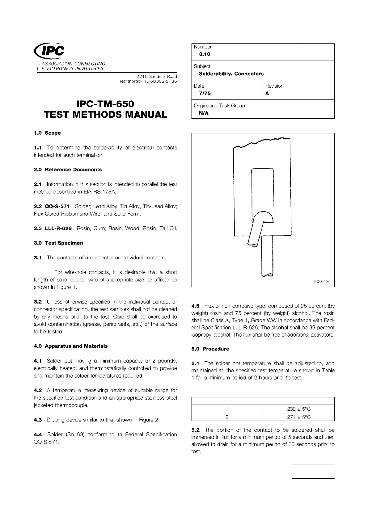
Figure 1 Wire Hole Termination
Material in this Test Methods Manual was voluntarily established by Technical Committees of the IPC. This material is advisory only
and its use or adaptation is entirely voluntary. IPC disclaims all liability of any kind as to the use, application, or adaptation of this
material. Users are also wholly responsible for protecting themselves against all claims or liabilities for patent infringement.
Equipment referenced is for the convenience of the user and does not imply endorsement by the IPC.
Page 1 of 2
ASSOCIATION
CONNECTING
/
ELECTRONICS
INDUSTRIES
221
5
Sanders
Road
Northbrook,
IL
60062-61
35
IPC-TM-650
TEST
METHODS
MANUAL
1
.0
Scope
1.1
To
determine
the
solderability
of
electrical
contacts
intended
for
such
termination.
2
.0
Reference
Documents
2.1
Information
in
this
section
is
intended
to
parallel
the
test
method
described
in
EIA-RS-1
78A.
2.2
QQ-S-571
Solder;
Lead
Alloy,
Tin
Alloy,
Tin-Lead
Alloy;
Flux
Cored
Ribbon
and
Wire,
and
Solid
Form.
2.3
LLL-R-626
Rosin,
Gum;
Rosin,
Wood;
Rosin,
Tall
Oil.
3
.0
Test
Specimen
3.1
The
contacts
of
a
connector
or
individual
contacts.
For
wire-hole
contacts,
it
is
desirable
that
a
short
length
of
solid
copper
wire
of
appropriate
size
be
affixed
as
shown
in
Figure
1
.
3.2
Unless
otherwise
specified
in
the
individual
contact
or
connector
specification,
the
test
samples
shall
not
be
cleaned
by
any
means
prior
to
the
test.
Care
shall
be
exercised
to
avoid
contamination
(grease,
perspirants,
etc.)
of
the
surface
to
be
tested.
4
.0
Apparatus
and
Materials
4.1
Solder
pot,
having
a
minimum
capacity
of
2
pounds,
electrically
heated,
and
thermostatically
controlled
to
provide
and
maintain
the
solder
temperatures
required.
4.2
A
temperature
measuring
device
of
suitable
range
for
the
specified
test
condition
and
an
appropriate
stainless
steel
jacketed
thermocouple.
4.3
Dipping
device
similar
to
that
shown
in
Figure
2.
4.4
Solder
(Sn
60)
conforming
to
Federal
Specification
QQ-S-571.
Number
3.10
Subject
Solderability,
Connectors
Date
Revision
7/75
A
Originating
Task
Group
N/A
r
r
1
IPC-3-10-1
4.5
Flux
of
non-corrosive
type,
composed
of
25
percent
(by
weight)
rosin
and
75
percent
(by
weight)
alcohol.
The
rosin
shall
be
Class
A,
Type
1
,
Grade
WW
in
accordance
with
Fed¬
eral
Specification
LLL-R-626.
The
alcohol
shall
be
99
percent
isopropyl
alcohol.
The
flux
shall
be
free
of
additional
activators.
5
.0
Procedure
5.1
The
solder
pot
temperature
shall
be
adjusted
to,
and
maintained
at,
the
specified
test
temperature
shown
in
Table
1
for
a
minimum
period
of
2
hours
prior
to
test.
1
232
±
5
℃
2
271
±
5
℃
5.2
The
portion
of
the
contact
to
be
soldered
shall
be
immersed
in
flux
for
a
minimum
period
of
5
seconds
and
then
allowed
to
drain
for
a
minimum
period
of
60
seconds
prior
to
test.