IPC-TM-650 EN 2022 试验方法--.pdf - 第801页
Sinusoidal Random Material in this T est Methods Manual was voluntarily established by T echnical Committees of the IPC. Thi s mate rial is ad visory o nly and its use or adaptation is entirely voluntary . IPC disclaims …
IPC-TM-650
Page 2 of 2
Number
3.11
Subject
Thermal
Shock,
Connectors
Date
7/75
Revision
A
6.3
Thermal
equilibrium
shall
be
assumed
to
have
been
attained
when
three
successive
temperature
readings
taken
at
five-minute
intervals
show
a
variation
not
greater
than
3
℃.
6.4
The
exposure
and
transfer
times
specified
in
Table
1
are
based
on
an
assumed
sample
weight
less
than
0.5
pound
(226
GMS).
Appropriate
increases
in
these
periods
shall
be
made
for
larger
samples
to
ensure
that
the
designated
test
temperature
is
attained.
Sinusoidal
Random
Material in this Test Methods Manual was voluntarily established by Technical Committees of the IPC. This material is advisory only
and its use or adaptation is entirely voluntary. IPC disclaims all liability of any kind as to the use, application, or adaptation of this
material. Users are also wholly responsible for protecting themselves against all claims or liabilities for patent infringement.
Equipment referenced is for the convenience of the user and does not imply endorsement by the IPC.
Page 1 of 6
r
ASSOCIATION
CONNECTING
/
ELECTRONICS
INDUSTRIES
2215
Sanders
Road
Northbrook,
IL
60062-6135
IPC-TM-650
TEST
METHODS
MANUAL
1
.0
Scope
1
.1
To
determine
the
effect
on
the
connector
of
the
stresses
produced
by
mechanical
vibration
within
the
predominant
fre¬
quency
ranges
and
of
amplitudes
that
may
be
encountered
during
field
service;
two
input
vibration
types
are
provided:
—
Used
to
determine
critical
frequencies,
modes
of
vibration,
and
other
data
necessary
for
planning
protective
steps
against
the
effects
of
undue
vibration.
The
simple
har¬
monic
motion
provided
by
this
method
is
not
representative
of
most
vibration
encountered
during
field
service.
—
Used
to
provide
a
closer
approximation
to
the
complex,
non-periodic
vibration
encountered
during
field
ser¬
vice.
2
.0
Reference
Documents
2.1
Information
in
this
section
is
intended
to
parallel
the
test
method
described
in
EIA-RS-364/TP-28.
3
.0
Test
Specimen
3.1
A
connector
(plug
and
receptacle)
complete
with
appli¬
cable
guide,
keying,
and
engaging
hardware
or
a
card
-edge
receptacle
and
mating
nominal-thickness
printed
circuit
board.
3.2
Mounting
and
Termination
3.2.1
Right
Angle,
Two-Piece
Connector
The
receptacle
shall
be
mounted
and
terminated
normally
during
this
test;
receptacles
designed
for
mounting
on
non-rigid
bases
(e.g.,
motherboards,
metal-plate
back
panels,
etc.)
shall
be
mounted
on
the
smallest
section
of
such
a
base
that
will
accommodate
the
test
specimen.
The
plug
shall
be
termi¬
nated
normally
during
this
test
and
shall
be
mounted
on
a
nominal-thickness
printed
circuit
board
extending
the
full
width
of
the
plug;
the
board
shall
extend
a
minimum
of
four
inches
from
the
receptacle
when
the
connector
is
mated.
3.2.2
Card-Edge
Receptacle
The
receptacle
shall
be
mounted
and
terminated
normally
during
this
test
(see
3.2.1
).
The
mating
printed
circuit
board
shall
extend
the
full
width
of
the
receptacle
and
shall
extend
a
minimum
of
four
inches
from
the
receptacle
when
mated.
Number
3.12
Subject
Vibration,
Connectors
Date
7/75
Revision
A
Originating
Task
Group
N/A
3.2.3
Parallel,
Two-Piece
Connector
The
receptacle
and
plug
shall
be
terminated
normally
during
this
test;
both
com¬
ponents
shall
be
mounted
on
nominal-thickness
printed
circuit
boards
extending
the
full
width
of
each.
The
printed
circuit
boards
shall
extend
a
minimum
of
four
inches
from
each
com¬
ponent
when
the
connector
is
mated.
3.3
Fixturing
3.3.1
Right
Angle
Connector
The
test
specimen
shall
be
held
in
an
adequate
resonant
free
fixture.
(Figure
1
,
Reference
example.)
3.3.2
Parallel
Connector
The
test
specimen
shall
be
held
in
an
adequate
resonant
free
fixture.
(Figure
2,
Reference
example.)
3.4
The
connector
shall
be
wired
(or
printed
circuit
boards
designed)
such
that
a
continuous
electrical
circuit
(comprising
all
contacts
in
series)
is
formed
when
the
plug
(or
board)
and
receptacle
are
mated.
4
.0
Apparatus
4.1
An
electrodynamics
vibration
system
and
associated
instrumentation
capable
of
producing
the
vibration
indicated
in
Table
1
and
Figures
3
and
4
as
specified
in
the
individual
con¬
nector
specification.
The
system
shall
be
capable
of
maintain¬
ing
the
vibratory
input
within
the
following
tolerances:
Displacement
-
土
1
0%
Acceleration
-
±
1
0%
Power
Spectral
Density
-
土
3.0
DB
(50
Hz
maximum
filter
bandwidth)
Frequency
-
±
2%
4.2
A
circuit
monitor
capable
of
supplying
a
continuous
cur¬
rent
of
1
00
milliamperes
and
of
detecting
discontinuities
in
this
current
greater
than
1
microsecond.
5
.0
Procedure
5.1
Calibration
5.1.1
The
vibration
system
shall
be
set
up
to
provide
the
sinusoidal
or
random
vibratory
input
in
accordance
with
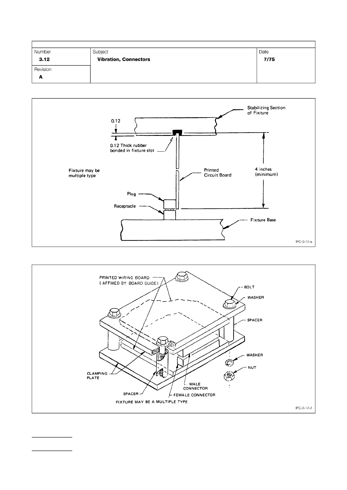
Figure 1 Right Angle Connector Fixture (Suggested)
Figure 2 Parallel Connector Fixture (Suggested)
IPC-TM-650
Page 2 of 6
Number
3.12
Subject
Vibration,
Connectors
Date
7/75
Revision
A
Fixture
may
be
multiple
type
I
PC-3-1
2-a
FIXTURE
MAY
BE
A
MULTIPLE
TYPE
IPC-3-12-2