IPC-TM-650 EN 2022 试验方法--.pdf - 第806页
EXAMPLE: EXAMPLE: IPC-TM-650 Page 6 of 6 Number 3.12 Subject Vibration, Connectors Date 7/75 Revision A B. The rate of change of frequency (Hz/min.) shall be con¬ stant for any one band. C. The ratio of the rate of chang…
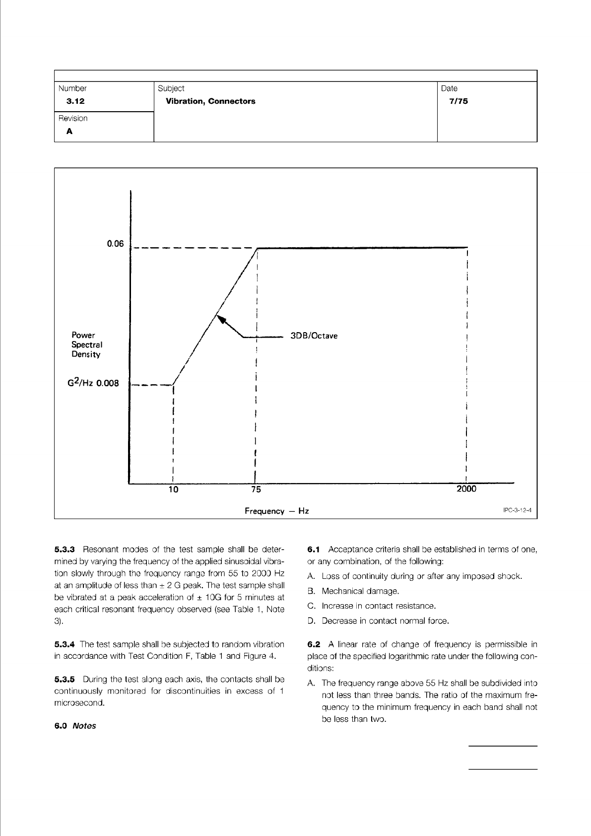
Figure 4 Random Vibration Input
IPC-TM-650
Page 5 of 6
Number
3.12
Subject
Vibration,
Connectors
Date
7/75
Revision
A
0.06
Power
Spectral
Density
G2/Hz
0.008
/1
'
/
>
>
3DB/Octave
|
/
|
।
/
,
!
(
;
1
:
i
;
1
i
1
1
1
i
1
L
10
75
2000
Frequency
—
Hz
ipc-3-12-4
5.3.3
Resonant
modes
of
the
test
sample
shall
be
deter¬
mined
by
varying
the
frequency
of
the
applied
sinusoidal
vibra¬
tion
slowly
through
the
frequency
range
from
55
to
2000
Hz
at
an
amplitude
of
less
than
±
2
G
peak.
The
test
sample
shall
be
vibrated
at
a
peak
acceleration
of
±
10G
for
5
minutes
at
each
critical
resonant
frequency
observed
(see
Table
1
,
Note
3).
5.3.4
The
test
sample
shall
be
subjected
to
random
vibration
in
accordance
with
Test
Condition
F,
Table
1
and
Figure
4.
5.3.5
During
the
test
along
each
axis,
the
contacts
shall
be
continuously
monitored
for
discontinuities
in
excess
of
1
microsecond.
6.1
Acceptance
criteria
shall
be
established
in
terms
of
one,
or
any
combination,
of
the
following:
A.
Loss
of
continuity
during
or
after
any
imposed
shock.
B.
Mechanical
damage.
C.
Increase
in
contact
resistance.
D.
Decrease
in
contact
normal
force.
6.2
A
linear
rate
of
change
of
frequency
is
permissible
in
place
of
the
specified
logarithmic
rate
under
the
following
con¬
ditions:
A.
The
frequency
range
above
55
Hz
shall
be
subdivided
into
not
less
than
three
bands.
The
ratio
of
the
maximum
fre¬
quency
to
the
minimum
frequency
in
each
band
shall
not
be
less
than
two.
6.0
Notes
EXAMPLE:
EXAMPLE:
IPC-TM-650
Page 6 of 6
Number
3.12
Subject
Vibration,
Connectors
Date
7/75
Revision
A
B.
The
rate
of
change
of
frequency
(Hz/min.)
shall
be
con¬
stant
for
any
one
band.
C.
The
ratio
of
the
rate
of
change
of
frequency
of
each
band
to
the
maximum
frequency
of
that
band
shall
be
approxi¬
mately
the
same
as
that
ratio
for
every
other
band.
As
an
example
of
the
computation
of
rates
of
change,
assume
that
the
frequency
spectrum
has
been
divided
into
three
bands,
55
to
125
Hz,
125
to
500
Hz,
and
500
to
2000
Hz,
in
accordance
with
6.2A.
Let
the
(constant)
ratio
of
rate
of
frequency
change
in
Hz/min.
to
maximum
frequency
in
Hz
be
k
for
each
band.
Then
the
rates
of
change
for
the
three
bands
will
be
125k,
500k
and
2000k,
respectively.
The
times,
in
minutes,
to
traverse
the
three
frequency
bands
will
therefore
be,
respectively,
125-55
500-125
and
2000-500
125k
500k
2000k
If
the
range
traverse
time
is
30
minutes
-
AC
二
70
375
+
1500
刃
二
125k
+
500k
-
2000k
from
which:
k
=
0.0687
The
required
maximum
constant
rates
of
frequency
change
for
the
three
bands
are
therefore
8.55,
34.2
and
137
Hz/min.,
respectively,
and
the
times
of
traverse
of
the
bands
are
8.2,
10.9
and
10.9
minutes,
respectively.
NOTE:
WARNING:
Material in this Test Methods Manual was voluntarily established by Technical Committees of the IPC. This material is advisory only
and its use or adaptation is entirely voluntary. IPC disclaims all liability of any kind as to the use, application, or adaptation of this
material. Users are also wholly responsible for protecting themselves against all claims or liabilities for patent infringement.
Equipment referenced is for the convenience of the user and does not imply endorsement by the IPC.
Page 1 of 2
r
ASSOCIATION
CONNECTING
/
ELECTRONICS
INDUSTRIES
2215
Sanders
Road
Northbrook,
IL
60062-6135
IPC-TM-650
TEST
METHODS
MANUAL
1
.0
Scope
1.1
To
determine
the
ability
of
the
connector
to
operate
safely
at
its
rated
voltage
and
to
withstand
momentary
over-
potentials
due
to
switching,
surges,
or
other
similar
phenom¬
ena.
The
dielectric
withstanding
voltage
test
is
also
called
high-potential,
over-potential,
or
dielectric-strength
test,
but
differs
from
a
dielectric-breakdown
test
as
described
in
para¬
graph
6.2.
2
.0
Reference
Documents
2.1
Information
in
this
section
is
intended
to
parallel
the
test
method
described
in
EIA-RS-364/TP-20.
3
.0
Specimen
3.1
A
plug,
receptacle
or
mated
combination
as
specified
in
the
individual
connector
specification.
4
.0
Apparatus
4.1
High
voltage
source
adjustable
to
within
±
5%
of
required
test
voltage
(DC
or
RMS)
and
capable
of
delivering
a
minimum
current
of
1
milliampere.
4.2
Leakage
current
meter
accurate
to
土
5%
of
reading.
Commercial
devices
are
available
that
incorporate
the
voltage
source
and
leakage
monitor,
as
well
as
a
fault
monitor
(e.g.,
light,
bell,
automatic
shut-down)
into
one
instru¬
ment.
4.3
Altitude
chamber
capable
of
maintaining
a
simulated
alti¬
tude
at
temperature
extremes
of
-65
to
+
1
25℃.
5
.0
Procedure
POTENTIALS
USED
DURING
THIS
TEST
MAY
PROVE
HAZARDOUS
TO
PERSONNEL
TAKE
PRECAU¬
TIONS
TO
PROTECT
PERSONNEL
FROM
ACCIDENTAL
EXPOSURE
TO
THESE
TEST
POTENTIALS.
Number
3.13
Subject
Withstanding
Voltage,
Connectors
Date
Revision
7/75
A
Originating
Task
Group
N/A
5
J
The
withstanding
voltage
shall
be
applied
between
indi¬
vidual
pairs
of
immediately
adjacent
contacts
and
between
the
shell
and/or
engaging
hardware
(if
they
exist)
and
the
closest
individual
contact(s).
The
method
of
connection
of
the
test
voltage
if
significant
shall
be
specified
in
the
individual
connec¬
tor
specification.
When
special
preparations
or
conditions
such
as
special
test
fixtures,
reconnection,
or
grounding
iso¬
lation
are
required,
they
shall
be
so
specified.
5.2
Under
the
specified
conditions
of
temperature
and
baro¬
metric
pressure,
the
test
voltage
shall
be
increased
from
zero
to
the
specified
value
as
uniformly
as
possible
at
an
approxi¬
mate
rate
of
500
volts
(DC
or
RMS)
per
second
unless
other¬
wise
specified.
5.3
The
test
voltage
shall
be
applied
for
a
minimum
period
of
60
seconds
during
which
time
the
connector
under
test
shall
be
observed
for
evidence
of
disruptive
discharge
or
for
leakage
current
in
excess
of
one
milliampere.
5.4
The
test
voltage
shall
be
gradually
reduced
to
zero
to
avoid
surges.
6
.0
Notes
6.1
Acceptance
criteria
shall
be
established
by
the
lack
of
disruptive
discharge
as
evidenced
by
flashover
(surface
dis¬
charge),
sparkover
(air
discharge),
or
breakdown
(puncture
discharge),
or
of
excessive
leakage
current.
Resistance
to
these
conditions
is
an
inherent
characteristic
of
connector
geometry
(e.g.,
contact
spacing),
contact
configuration
(e.g.,
smooth
contours),
and
insulator
materials.
6.2
Dielectric
withstanding
voltage
shall
be
defined
as
75
percent
of
the
nominal
dielectric
breakdown
voltage
mea¬
sured
under
the
same
conditions
of
altitude
and
temperature.
6.3
Simulated
altitudes
used
during
this
test
shall
be
selected
from
those
shown
in
Table
1
.