IPC-TM-650 EN 2022 试验方法--.pdf - 第812页
Note: Figure 1 Fretting Motion to be Applied to PCB Connectors Material in this T est Methods Manual was voluntarily established by T echnical Committees of the IPC. Thi s mate rial is ad visory o nly and its use or adap…
Material in this Test Methods Manual was voluntarily established by Technical Committees of the IPC. This material is advisory only
and its use or adaptation is entirely voluntary. IPC disclaims all liability of any kind as to the use, application, or adaptation of this
material. Users are also wholly responsible for protecting themselves against all claims or liabilities for patent infringement.
Equipment referenced is for the convenience of the user and does not imply endorsement by the IPC.
Page 1 of 1
r
ASSOCIATION
CONNECTING
/
ELECTRONICS
INDUSTRIES
2215
Sanders
Road
Northbrook,
IL
60062-6135
IPC-TM-650
TEST
METHODS
MANUAL
1
Scope
This
test
method
is
used
to
determine
if
the
dielectric
materials
are
nutrient
to
specific
fungus
microorgan¬
isms.
2
Applicable
Documents
None
3
Test
Specimen
3.1
The
test
specimen
must
be
at
least
one
end
product
connector.
4
Equipment/Apparatus
4.1
Autoclave
capable
of
maintaining
30℃
and
95%
RH
and
an
ultraviolet
(3600
angstroms)
source
for
subsequent
decontamination
4.2
Microorganisms
4.2.1
Choetomium
globosum
No.
6205
4.2.2
Memnoniella
flavus
No.
11973
4.2.3
Aspergillus
flavus
No.
1
0836
4.2.4
Penicillum
citrinum
No.
9849
4.3
Microscope
capable
of
18X
5
Procedure
5.1
Preparation
5.1.1
All
glassware,
inoculating
loops,
pipettes,
etc.,
must
be
sterilized
at
117
Kp
and
1
35℃
prior
to
commencing
any
phase
of
the
test.
5.1.2
Use
each
one
of
the
fungus
microorganisms
for
a
composite
spore
suspension.
5.1.3
The
spore
suspension
must
be
used
within
24
hours
at
temperatures
between
22℃
to
32℃
and
can
be
stored
for
a
maximum
of
48
hours
at
1
.67℃
to
7.22℃.
5.1.4
Prepare
25
ml
of
distilled
water
having
a
pH
value
from
5.8
to
7.2
at
temperatures
between
22℃
to
32℃.
Number
3.15
Subject
Fungus
Resistance,
Connectors
Date
Revision
3/79
Originating
Task
Group
5.1.5
Introduce
1.0
ml
of
distilled
water
into
each
tube
of
fungi
and
gently
rub
the
spore
layer
with
a
sterilized
inoculat¬
ing
loop
without
disturbing
the
agar
surface.
5.1.6
Pour
the
four
solutions
in
a
sterilized
Florence
flask
containing
100
ml
of
distilled
water
and
mix
the
suspension
thoroughly.
5.2
Test
5.2.1
Set
the
autoclave
at
30℃
and
95%
RH
and
stabilize
for
a
minimum
of
two
hours.
5.2.2
Place
the
specimen
in
the
chamber
and
spray
all
of
the
test
surfaces
thoroughly,
using
the
250
ml
Florence
flask
and
atomizer
attachment.
5.2.3
Operate
the
chamber
for
28
days,
observe
and
note
fungus
growth
daily.
(Do
not
remove
the
specimen
from
the
chamber
for
prolonged
periods.)
5.2.4
After
exposure,
examine
all
surfaces
through
an
1
8X
microscope.
5.3
Evaluation
5.3.1
Report
the
specimens
that
were
found
to
be
nutrient
to
fungus
growth.
5.3.2
Corrosion
should
be
noted
separately
from
the
fungus
test
results.
6
Notes
6.1
After
exposure
and
subsequent
examinations,
the
mate¬
rials,
equipment,
component
or
part,
and
the
test
chamber
must
be
decontaminated
by
exposure
on
all
sides
to
ultravio¬
let
rays
(3600
angstroms)
for
a
minimum
of
two
hours,
or
sprayed
with
a
solution
of
1
:750
zephiran
chloride.
(One
part
zephiran
chloride
to
750
parts
distilled
water.)
6.2
Microorganisms
available
from:
AMERICAN
TYPE
CULTURE
2301
Parklawn
Drive
Rockville,
MD
20852
Note:
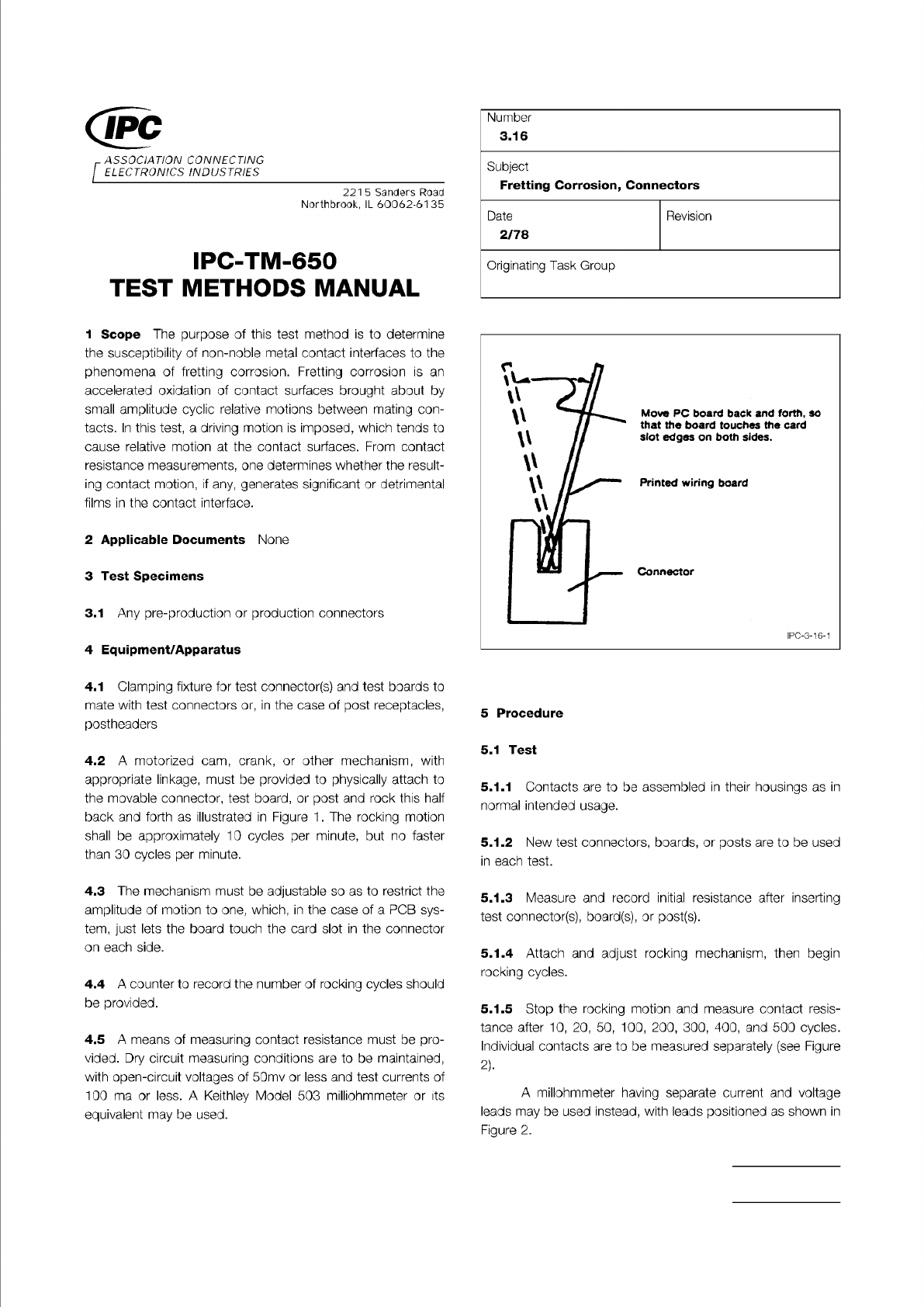
Figure 1 Fretting Motion to be Applied to PCB
Connectors
Material in this Test Methods Manual was voluntarily established by Technical Committees of the IPC. This material is advisory only
and its use or adaptation is entirely voluntary. IPC disclaims all liability of any kind as to the use, application, or adaptation of this
material. Users are also wholly responsible for protecting themselves against all claims or liabilities for patent infringement.
Equipment referenced is for the convenience of the user and does not imply endorsement by the IPC.
Page 1 of 2
ASSOCIATION
CONNECTING
/
ELECTRONICS
INDUSTRIES
221
5
Sanders
Road
Northbrook,
IL
60062-61
35
IPC-TM-650
TEST
METHODS
MANUAL
1
Scope
The
purpose
of
this
test
method
is
to
determine
the
susceptibility
of
non-noble
metal
contact
interfaces
to
the
phenomena
of
fretting
corrosion.
Fretting
corrosion
is
an
accelerated
oxidation
of
contact
surfaces
brought
about
by
small
amplitude
cyclic
relative
motions
between
mating
con¬
tacts.
In
this
test,
a
driving
motion
is
imposed,
which
tends
to
cause
relative
motion
at
the
contact
surfaces.
From
contact
resistance
measurements,
one
determines
whether
the
result¬
ing
contact
motion,
if
any,
generates
significant
or
detrimental
films
in
the
contact
interface.
2
Applicable
Documents
None
3
Test
Specimens
3.1
Any
pre-production
or
production
connectors
4
Equipment/Apparatus
4.1
Clamping
fixture
for
test
connector(s)
and
test
boards
to
mate
with
test
connectors
or,
in
the
case
of
post
receptacles,
postheaders
4.2
A
motorized
cam,
crank,
or
other
mechanism,
with
appropriate
linkage,
must
be
provided
to
physically
attach
to
the
movable
connector,
test
board,
or
post
and
rock
this
half
back
and
forth
as
illustrated
in
Figure
1
.
The
rocking
motion
shall
be
approximately
10
cycles
per
minute,
but
no
faster
than
30
cycles
per
minute.
4.3
The
mechanism
must
be
adjustable
so
as
to
restrict
the
amplitude
of
motion
to
one,
which,
in
the
case
of
a
PCB
sys¬
tem,
just
lets
the
board
touch
the
card
slot
in
the
connector
on
each
side.
4.4
A
counter
to
record
the
number
of
rocking
cycles
should
be
provided.
4.5
A
means
of
measuring
contact
resistance
must
be
pro¬
vided.
Dry
circuit
measuring
conditions
are
to
be
maintained,
with
open-circuit
voltages
of
50mv
or
less
and
test
currents
of
100
ma
or
less.
A
Keithley
Model
503
milliohmmeter
or
its
equivalent
may
be
used.
Number
3.16
Subject
Fretting
Corrosion,
Connectors
Date
Revision
2/78
Originating
Task
Group
Move
PC
board
back
and
forth,
so
that
the
board
touches
the
card
slot
edges
on
both
sides.
Printed
wiring
board
Connector
IPC-3-16-1
5
Procedure
5.1
Test
5.1.1
Contacts
are
to
be
assembled
in
their
housings
as
in
normal
intended
usage.
5.1.2
New
test
connectors,
boards,
or
posts
are
to
be
used
in
each
test.
5.1.3
Measure
and
record
initial
resistance
after
inserting
test
connector(s),
board(s),
or
post(s).
5.1.4
Attach
and
adjust
rocking
mechanism,
then
begin
rocking
cycles.
5.1.5
Stop
the
rocking
motion
and
measure
contact
resis¬
tance
after
10,
20,
50,
100,
200,
300,
400,
and
500
cycles.
Individual
contacts
are
to
be
measured
separately
(see
Figure
2).
A
millohmmeter
having
separate
current
and
voltage
leads
may
be
used
instead,
with
leads
positioned
as
shown
in
Figure
2.
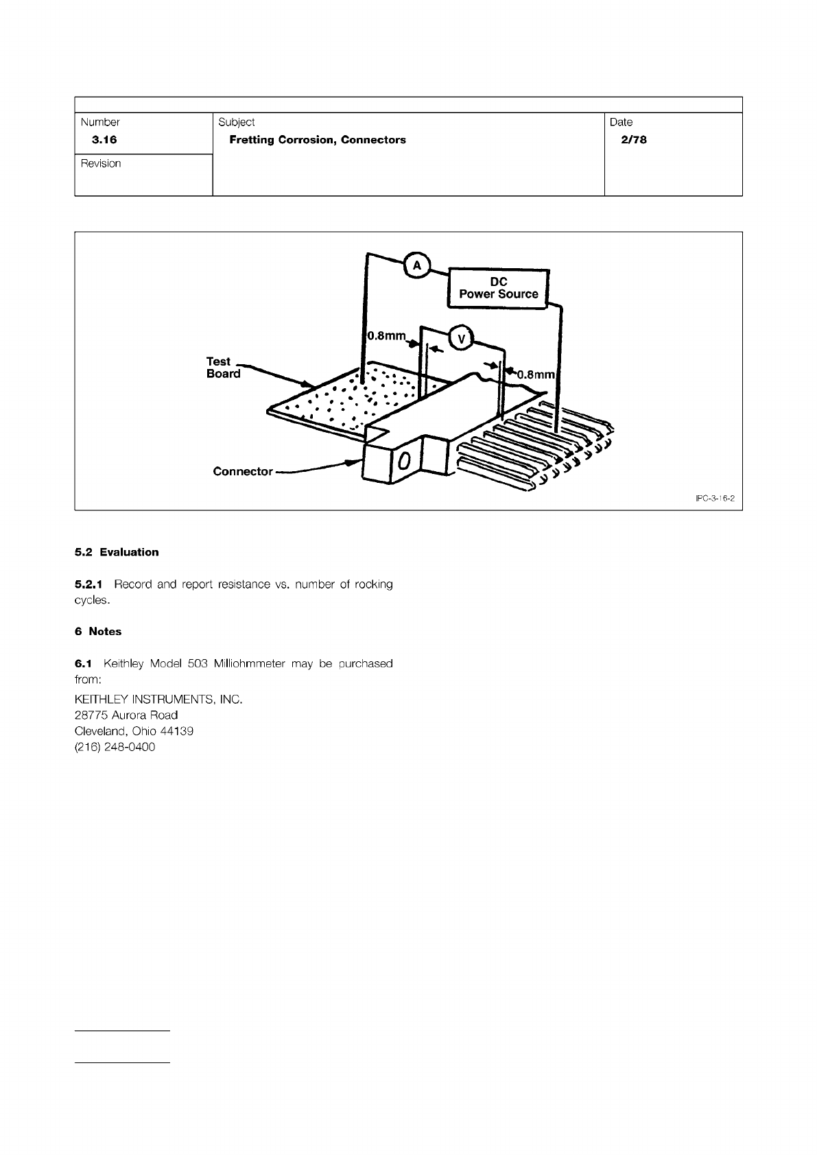
Figure 2 Method of Making Contact Resistance Measurements
IPC-TM-650
Page 2 of 2
Number
3.16
Subject
Fretting
Corrosion,
Connectors
Date
2/78
Revision
5.2
Evaluation
5.2.1
Record
and
report
resistance
vs.
number
of
rocking
cycles.
6
Notes
6.1
Keithley
Model
503
Milliohmmeter
may
be
purchased
from:
KEITHLEY
INSTRUMENTS,
INC.
28775
Aurora
Road
Cleveland,
Ohio
44139
(216)
248-0400