IPC-TM-650 EN 2022 试验方法--.pdf - 第814页
Material in this T est Methods Manual was voluntarily established by T echnical Committees of the IPC. Thi s mate rial is ad visory o nly and its use or adaptation is entirely voluntary . IPC disclaims all lia bility of …
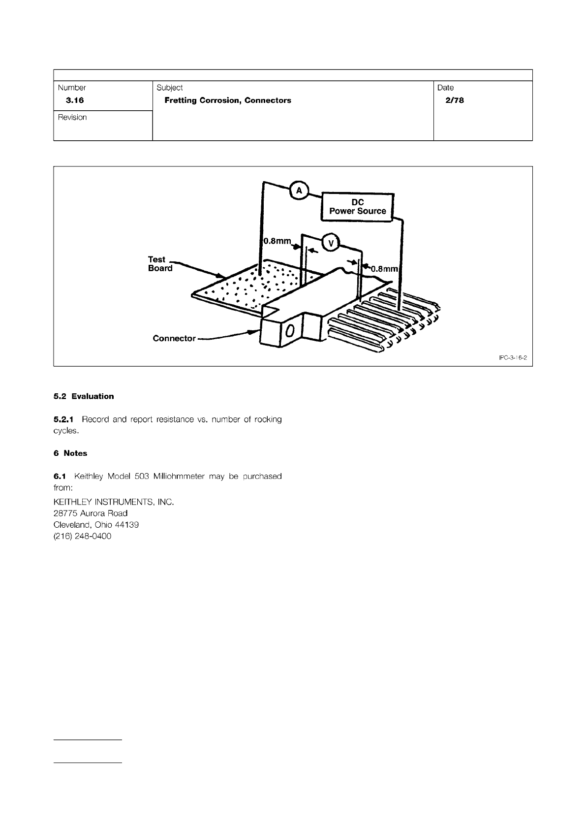
Figure 2 Method of Making Contact Resistance Measurements
IPC-TM-650
Page 2 of 2
Number
3.16
Subject
Fretting
Corrosion,
Connectors
Date
2/78
Revision
5.2
Evaluation
5.2.1
Record
and
report
resistance
vs.
number
of
rocking
cycles.
6
Notes
6.1
Keithley
Model
503
Milliohmmeter
may
be
purchased
from:
KEITHLEY
INSTRUMENTS,
INC.
28775
Aurora
Road
Cleveland,
Ohio
44139
(216)
248-0400
Material in this Test Methods Manual was voluntarily established by Technical Committees of the IPC. This material is advisory only
and its use or adaptation is entirely voluntary. IPC disclaims all liability of any kind as to the use, application, or adaptation of this
material. Users are also wholly responsible for protecting themselves against all claims or liabilities for patent infringement.
Equipment referenced is for the convenience of the user and does not imply endorsement by the IPC.
Page 1 of 1
r
ASSOCIATION
CONNECTING
/
ELECTRONICS
INDUSTRIES
2215
Sanders
Road
Northbrook,
IL
60062-6135
IPC-TM-650
TEST
METHODS
MANUAL
1
Scope
This
test
method
is
used
to
determine
the
effects
of
long
term
operation
of
components
in
atmospheres
con¬
taining
industrial
gaseous
pollutants.
It
consists
of
exposure
to
a
flowing-gas
humid
atmosphere
containing
SO2,
H2S,
and
H02
in
concentrations
of
200
parts
per
billion
(ppb).
This
cor¬
responds
to
a
worst-case
polluted
atmosphere,
and
is
an
accelerated
exposure
to
normal,
average
pollutant
level
atmo¬
sphere.
An
acceleration
factor
of
30-40
is
associated
with
this
test.
1
.2
To
further
simulate
and
accelerate
conditions
obtained
in
operating
environments,
the
test
also
involves
temperature
and
humidity
cycling,
so
as
to
cause
breathing
and
moisture
condensation
on
the
test
samples.
2
Applicable
Documents
None
3
Test
Specimen
3.1
Any
pre-production
or
production
samples
wired
and
mated
as
intended
for
actual
use
4
Apparatus
4.1
Test
chamber
and
its
associated
control
equipment
capable
of
producing
and
maintaining
the
conditions
of
4.1
.1
and
4.1
.2
4.1.1
Capable
of
cycling
the
temperature
between
68℃
and
26℃
with
the
following
schedule:
Eight
hours
at
68℃
One
hour
transition
to
26℃
Two
hours
at
26℃
One
hour
transition
to
68℃
These
1
2-hour
cycles
are
to
be
repeated
continuously
for
the
duration
of
time
specified
for
the
exposure.
4.1.2
Capable
of
maintaining
80%
RH
±
5%
RH
during
the
68℃
dwell
time.
Uncontrolled
during
temperature
transitions
so
as
to
allow
condensation
on
the
samples.
Number
3.17
Subject
Industrial
Gas
Test
(Battelle
Method),
Connectors
Date
Revision
2/78
Originating
Task
Group
4.2
Gaseous
Atmospheric
Pollutants
Concentrations
of
200
ppb
in
normal
air
(N2
-
20%
02)
of
the
following
pollutants
shall
be
maintained
in
the
exposure
chamber
at
all
times:
H
2s
(200
ppb)
S02
(200
ppb)
N02
(200
ppb)
A
convenient
and
satisfactory
way
of
producing
this
environ¬
ment
is
the
"Battelle
Flowing
Gas
System.”
In
this
system,
the
pollutant
concentrations
are
maintained
through
the
use
of
permeation
tubes,
which
are
small
Teflon
tubing
sections,
about
2
cm
long,
sealed
at
both
ends,
and
containing
the
pol¬
lutant
of
interest
as
a
liquid
at
room
temperature.
These
per¬
meation
tubes
are
placed
in
the
main
air
stream,
which
feeds
the
exposure
chamber,
and
the
concentrations
of
the
pollut¬
ants
are
determined
by
the
diffusion
rates
of
the
gas
out
of
the
permeation
tubes.
At
a
constant
flow
rate
and
temperature
of
the
main
air
stream,
the
concentration
of
pollutants
will
be
constant.
Periodic
weighing
of
the
permeation
tubes
may
do
pollutant
gas
“analysis.”
The
flow
rate
of
the
main
air
stream
is
such
that
the
exposure
chamber
volume
is
exchanged
approximately
every
30
min¬
utes.
5
Procedure
5.1
Wire
and
mate
the
test
specimen
as
in
normal
intended
operation
during
exposure
in
this
test.
5.2
The
duration
of
this
test
is
generally
calculated
from
the
expected
service
lifetime
of
the
product.
5.3
The
actual
duration
of
this
exposure
is
to
be
determined
between
vendor
and
user
and/or
is
a
part
of
the
applicable
product
specification.
A
60-day
exposure
in
this
test
corre¬
sponds
to
approximately
six
years
of
exposure
in
normal
industrial
environments.
6
Notes
6.1
Reference
Abbott,
W.
H.,
Effects
of
Industrial
Air
Pol¬
lutants
on
Electrical
Contact
Materials,
Holm
Seminar
on
Elec¬
tric
Contact
Phenomena,
November
1973.
Material in this Test Methods Manual was voluntarily established by Technical Committees of the IPC. This material is advisory only
and its use or adaptation is entirely voluntary. IPC disclaims all liability of any kind as to the use, application, or adaptation of this
material. Users are also wholly responsible for protecting themselves against all claims or liabilities for patent infringement.
Equipment referenced is for the convenience of the user and does not imply endorsement by the IPC.
Page 1 of 2
r
ASSOCIATION
CONNECTING
/
ELECTRONICS
INDUSTRIES
2215
Sanders
Road
Northbrook,
IL
60062-6135
IPC-TM-650
TEST
METHODS
MANUAL
1
Scope
This
test
method
is
used
to
determine
the
mechanical
forces
required
to
mate
connectors
before
and
after
the
connectors
are
subjected
to
various
environmental
stresses.
2
Applicable
Documents
None
3
Test
Specimen
3.1
One
piece
connector
(plug
and
receptacle),
complete
with
all
applicable
guide,
keying,
and
engaging
hardware
or
a
carot
edge
receptacle
3.2
Two
piece
connector
(header
and
receptacle
or
plug
and
receptacle),
complete
with
all
applicable
guide,
keying,
and
engaging
hardware
and
appropriate
flat
cable
3.3
Unless
otherwise
specified
in
the
individual
connector
specification,
the
test
samples
(or
engaging
hardware)
shall
not
be
lubricated
or
otherwise
coated
prior
to
the
test.
4
Apparatus
4.1
Test
blade
as
shown
in
Figure
1,
to
simulate
a
mating
PWB
of
maximum
thickness
for
card
edge
(one-piece)
con¬
nector
4.2
Mating
connector
to
test
for
mating
and
unmating
force
of
two
piece
connectors
4.3
Force
gauges
of
applicable
range
4.4
Clamps,
jaws,
or
other
means
to
hold
the
receptacle
and
header
or
receptacle
and
plug
Number
3.18
Subject
Mating
and
Unmating
Force,
Connectors
Date
Revision
1/83
Originating
Task
Group
4.5
Automatic
or
semi-automatic
tester
to
mate
and
unmate
the
connector
at
the
specified
rate.
Note:
While
manual
cycling
of
the
connectors
is
permitted,
proper
alignment
and
orientation
is
most
readily
maintained
in
a
mechanical
device
specifically
designed
for
this
test.
5
Procedure
5
J
The
samples
shall
be
mounted
in
the
tester
and
carefully
aligned.
5
.2
Mating
Force
The
samples
shall
be
brought
to
a
posi¬
tion
where
mechanical
mating
begins
and
the
force
gauge
is
at
zero
indication.
The
samples
shall
then
be
fully
mated
and
the
force
required
for
mating
shall
be
recorded.
5
.3
Unmating
Force
Once
the
mechanical
mating
is
com¬
plete
and
the
force
gage
is
at
zero
indication,
the
samples
shall
be
separated
and
the
force
required
for
separation
shall
be
recorded.
5
.4
At
the
intervals
specified
in
the
individual
connector
specification,
inspections
or
tests
may
be
performed.
5
.5
During
the
final
cycle,
the
force
required
for
both
mating
and
unmating
shall
again
be
recorded.
6
Notes
6.1
Acceptance
criteria
shall
be
established
in
terms
of
the
maximum
allowable
total
mating
force
and
the
minimum
allowable
total
separation
force
during
the
test.
6.2
The
information
in
this
test
method
is
intended
to
paral¬
lel
the
test
method
described
in
EIA-RS-364/TP-1
3.