PPS Pro version 8.2 - 第104页
User Manual 4022 591 98247 100 PPS-Pro v8.2 05.07 Guidelines for using PPS-Pro 3.2.10 Miscellaneous 3.2.10.1 C:\temp dire ctory does not exist ■ Description: If th e ‘C:\temp’ direct ory doesn’t e xist, the f ollowi ng e…

4022 591 98247 User Manual
05.07 PPS-Pro v8.2 99
Guidelines for using PPS-Pro
3.2.8.1 Fiducial arrangement and bad mark groups
Fiducial arrangement and bad mark groups is implemented with the following
restrictions:
■ The PPS-Pro FCM optimizer will only generate action specifications for a
line containing all extended FCM (extended BVM and CLM) machines or all
non-extended FCM machines. If a combined line is used, the extended FCM
machines are seen as non-extended FCM machines.
■ The CAD data must contain circuit information (it may not be flattened),
check this as follows: in the MDF file the copies of circuits are only shown
by their Step and Repeat points. Only then fiducial arrangements and bad
mark groups can be created (in group mode). The introduction of the
fiducial arrangements and bad mark groups will not affect the action spec
-
ification generation of the ACM.
■ A circuit (with a circuit bad mark) may belong to at most ONE bad mark
group. In fiducial arrangement, a circuit should belong to two circuit
fiducial arrangements.
3.2.9 Transport Settings
3.2.9.1 Max. amount of transport steps
■ Description: It is possible to specify 10 index steps in each project of PPS-
Pro for FCM. All 10 steps become available in the action spec. after optimi
-
zation. However the action spec. format of the FCM can only handle 9
index steps. The FCM generates the following error: "Action Spec error on
transport". FCM MF can only handle 7 index steps
■ Advice: Do not specify more than 9 tranport steps for FCM. If FCM MF of
FCM ME is used only 7 transport steps can be used.
3.2.9.2 Do not specify “<none>”
■ Description: Some old transport settings have “<none>” specified as an
index step. However the PowerLine™ PPS-Pro can not handle “<none>”. It
produces an unclear error in the equip.dat file.
■ Advice: Do not specify “<none>” as a transport step, or remove “<none>”
if it is specified as a transport step.
3.2.9.3 Settings in ALE does not work
■ Description: In normal circumstances the default index schemes are used.
However if a special index scheme is required it can only be specified in
the PPS Machine Specific settings. Defining transport settings in the ALE
file does not work.
■ Advice: If a special index scheme is required specify it in the PPS Machine
Specific settings.

User Manual 4022 591 98247
100 PPS-Pro v8.2 05.07
Guidelines for using PPS-Pro
3.2.10 Miscellaneous
3.2.10.1 C:\temp directory does not exist
■ Description: If the ‘C:\temp’ directory doesn’t exist, the following error
occurs: ‘Optimizer Error: 1001: Error created directory C:\TEMP\emt_temp,
status -1’.
■ Advice: Create the ‘C:\temp’ directory.
3.2.10.2 BVM1Index - Set Attributes
When the ‘BVM1Index’ is set to ‘Yes’ in the ALE attributes then it indicates
that all fiducial actions which belong together (for a circuit or group) must be
done in the same index step. Because the transport system performs no inter
-
mediate steps between the BVM measurements, the correction for the
particular fiducial arrangement is more accurate, and therefore leads to a
better placement accuracy. This does not mean that the BVM actions must be
done in the first index.
3.2.11 How to use transport settings for FCM
The transport of a pcb through an FCM is carried out by the transport beam
with a carrier set on it. In normal circumstances the default index schemes
(see 3.2.11.1 on page 100) are used. However if a special index scheme is
required it can be specified in the PPS Machine Specific settings.
Every step of the scheme represents a step (move in x-direction) of the beam
in an FCM.
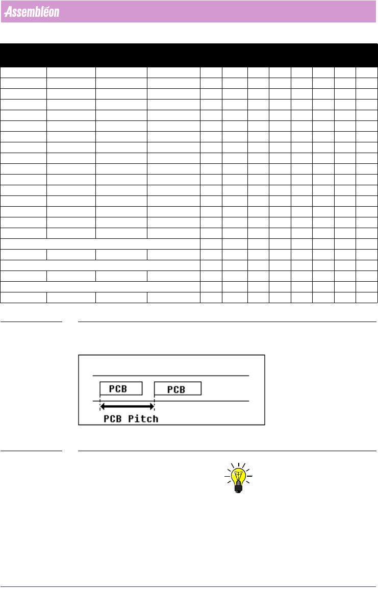
3.2.11.1 Default FCM index schemes
These values are tuned for ‘DFA/BMS’ usage on the FCM (see TABLE 6 on page
101).
Pitch Max X PCB
Stopper in X
position
Boards
index step size (mm)
x01 x02xx03xx04xx05xx06xx07xx08
120 114 -341 20 60 60
130 124 -301 18 60 70
140 134 -201 16 70 70
150 144 -311 16 70 80
160 154 -301 15 80 80
170 164 -271 14 50 60 60
180 174 -261 13 60 60 60
190 184 -191 12 60 60 70
200 194 -281 12 60 70 70
210 204 -201 11 70 70 70
220 214 -261 11 70 70 80
4022 591 98247 User Manual
05.07 PPS-Pro v8.2 101
Guidelines for using PPS-Pro
TABLE 6 Default FCM index schemes
SCREEN 60 PCB Pitch
NOTE: Use alternative if these constraints can not be obeyed.
1) The second fiducial (left) can be reached in index 1 if the distance between
second fiducial (left) and the SE point is less than 380 mm.
2) The second fiducial (left) can be reached in index 1 if the distance between
second fiducial (left) and the SE point is less than 400 mm.
230 224 -171 10 70 80 80
240 234 -221 10 80 80 80
250 244 -101 9 60 60 60 70
260 254 -181 9 60 60 60 80
270 264 -221 9 60 60 70 80
280 274 -101 8 60 60 80 80
290 284 -161 8 70 70 70 80
300 294 -161 8 70 70 80 80
310 304 -171 8 70 80 80 80
320 314 -101 7 60 60 60 60 80
330 324 -101 7 60 60 70 70 70
340 334 -121 7 60 80 80 60 60
350 344 -161 7 80 80 70 60 60
360 354 -161 7 80 80 80 60 60
380 374 -41 6 0 60 80 80 80 80
400
1
394 -121 6 60 60 60 60 80 80
Alternative 60 60 20 60 60 70 70
420
2
414 -101 6 60 60 80 80 70 70
Alternative 60 30 30 80 80 70 70
460
3
454 -41 5 0 60 80 80 80 80 80
Alternative (Not for FCM MF/ME) 0 60 0 80 80 80 80 80
480
4
474 -41 5 0 80 80 80 80 80 80
Pitch Max X PCB
Stopper in X
position
Boards
index step size (mm)
x01 x02xx03xx04xx05xx06xx07xx08