PPS Pro version 8.2 - 第106页
User Manual 4022 591 98247 102 PPS-Pro v8.2 05.07 Guidelines for using PPS-Pro 3) The secon d fiducial (left) can be rea ched in inde x 1 if the distance betw een second fidu cial (left) and the SE poin t is less than 40…
4022 591 98247 User Manual
05.07 PPS-Pro v8.2 101
Guidelines for using PPS-Pro
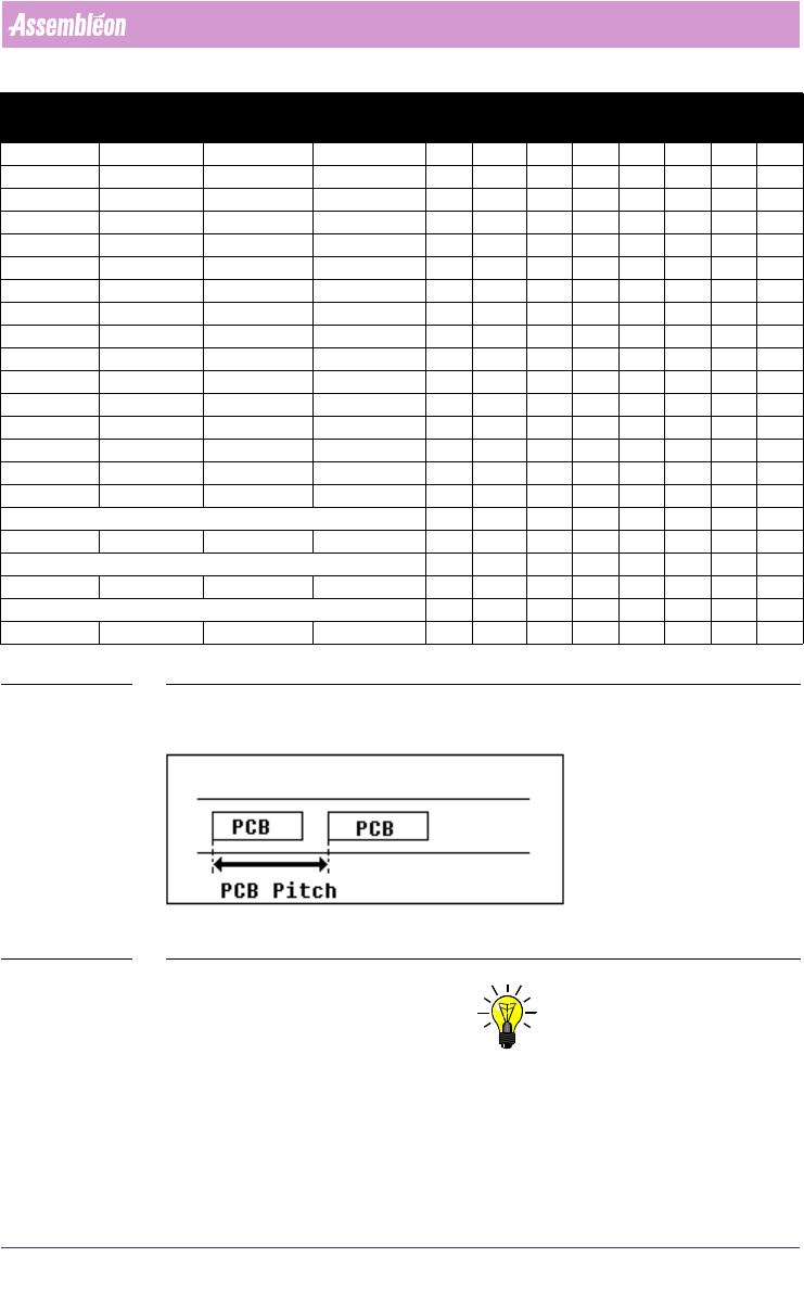
TABLE 6 Default FCM index schemes
SCREEN 60 PCB Pitch
NOTE: Use alternative if these constraints can not be obeyed.
1) The second fiducial (left) can be reached in index 1 if the distance between
second fiducial (left) and the SE point is less than 380 mm.
2) The second fiducial (left) can be reached in index 1 if the distance between
second fiducial (left) and the SE point is less than 400 mm.
230 224 -171 10 70 80 80
240 234 -221 10 80 80 80
250 244 -101 9 60 60 60 70
260 254 -181 9 60 60 60 80
270 264 -221 9 60 60 70 80
280 274 -101 8 60 60 80 80
290 284 -161 8 70 70 70 80
300 294 -161 8 70 70 80 80
310 304 -171 8 70 80 80 80
320 314 -101 7 60 60 60 60 80
330 324 -101 7 60 60 70 70 70
340 334 -121 7 60 80 80 60 60
350 344 -161 7 80 80 70 60 60
360 354 -161 7 80 80 80 60 60
380 374 -41 6 0 60 80 80 80 80
400
1
394 -121 6 60 60 60 60 80 80
Alternative 60 60 20 60 60 70 70
420
2
414 -101 6 60 60 80 80 70 70
Alternative 60 30 30 80 80 70 70
460
3
454 -41 5 0 60 80 80 80 80 80
Alternative (Not for FCM MF/ME) 0 60 0 80 80 80 80 80
480
4
474 -41 5 0 80 80 80 80 80 80
Pitch Max X PCB
Stopper in X
position
Boards
index step size (mm)
x01 x02xx03xx04xx05xx06xx07xx08

User Manual 4022 591 98247
102 PPS-Pro v8.2 05.07
Guidelines for using PPS-Pro
3) The second fiducial (left) can be reached in index 1 if the distance between
second fiducial (left) and the SE point is less than 400 mm. (Not for FCM MF/
ME)
4) The second fiducial (left) MUST be reached in index 1 if the distance
between the second fiducial (left) and the SE point is less than 400 mm. If not
DFA is not possible.
NOTE: Transport lift-up position equals –440 mm for all schemes. In these cases
‘stopper out’ must be used, so in the Machine or MachineClass attributes
section write: ‘TransportStopperOutUsed’ ‘YES’
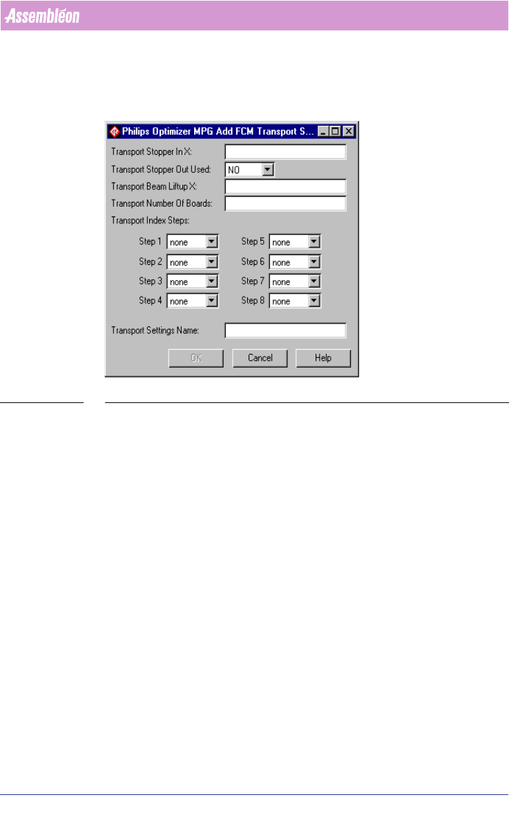
3.2.11.2 Specify custom index scheme
If a special index scheme is required it can be specified in the PPS Machine
Specific settings
(see 3.2.11.3 on page 102).
Important parameters which must be defined are described below.
• TransportStopperInX: An integer that specifies the X location of the
transport run-in stopper, relative to the machine origin.
• TransportStopperOutUsed: Specifies whether the run-out stopper
should be used. Possible values are ‘Yes’ and ‘No’.
• TransportBeamLiftupX: An integer that specifies the X location of the
beam liftup, relative to the machine origin.
• TransportNrOfBoards: An integer that indicates the number of boards
on the beam.
• TransportIndexStep: Specifies an array of integer values representing
the index steps (maximum 10 values). The sum of these steps
determine the board pitch.
There is a special order of importance of the specified index schemes, 1
overrules 2:
1. User defined project related transport settings (see 3.2.11.3 on page 102).
2. PPS defines default index schemes.
3.2.11.3 Specify project related transport settings
To specify the transport settings via the GUI of PPS-Pro the following things
must be done. Refer to Specify Project related optimizer settings
(see 2.25.1
on page 61).
To specify a new index scheme press the Add... button and the Add FCM
Transport Setting dialog appears
(see SCREEN 61 on page 103). Just fill in
every field in this dialog. After everything is specified, the name of the index
4022 591 98247 User Manual
05.07 PPS-Pro v8.2 103
Guidelines for using PPS-Pro
scheme must be filled in the Transport Settings Name textbox. After pressing
the OK button, the transport settings are added to the FCM Transport
Settings frame. The specified index scheme will be joined with the currently
specified machine in the Program Machine tab of PPS-Pro.
SCREEN 61 Add Transport Setting
3.2.11.4 Reference Pins Positions
This paragraph describes the default values for the reference pin positions for
the FCM Multiflex machine.
Two reference pins are in use (out of 4 possible pins) namely the right hand
reference pin and the left hand reference pin. The co-ordinates (x,y) for right
and left hand reference pins must be specified in ‘mm’ and measured with
respect to the south-east corner of the PCB
(see SCREEN 62 on page 104).
Reference pin pitch is equal to the PCB pitch.
Refer to the manual “Description ALE-file 12NC 4022 591 98715” for infor-
mation on how to set this parameters.