PPS Pro version 8.2 - 第108页
User Manual 4022 591 98247 104 PPS-Pro v8.2 05.07 Guidelines for using PPS-Pro SCREEN 62 Referen ce Pin P os ition s SCREEN 63 Referen ce Pin P osition s Measur emen t NOTE: In most cases the DEFAULT for the ri ght refer…
4022 591 98247 User Manual
05.07 PPS-Pro v8.2 103
Guidelines for using PPS-Pro
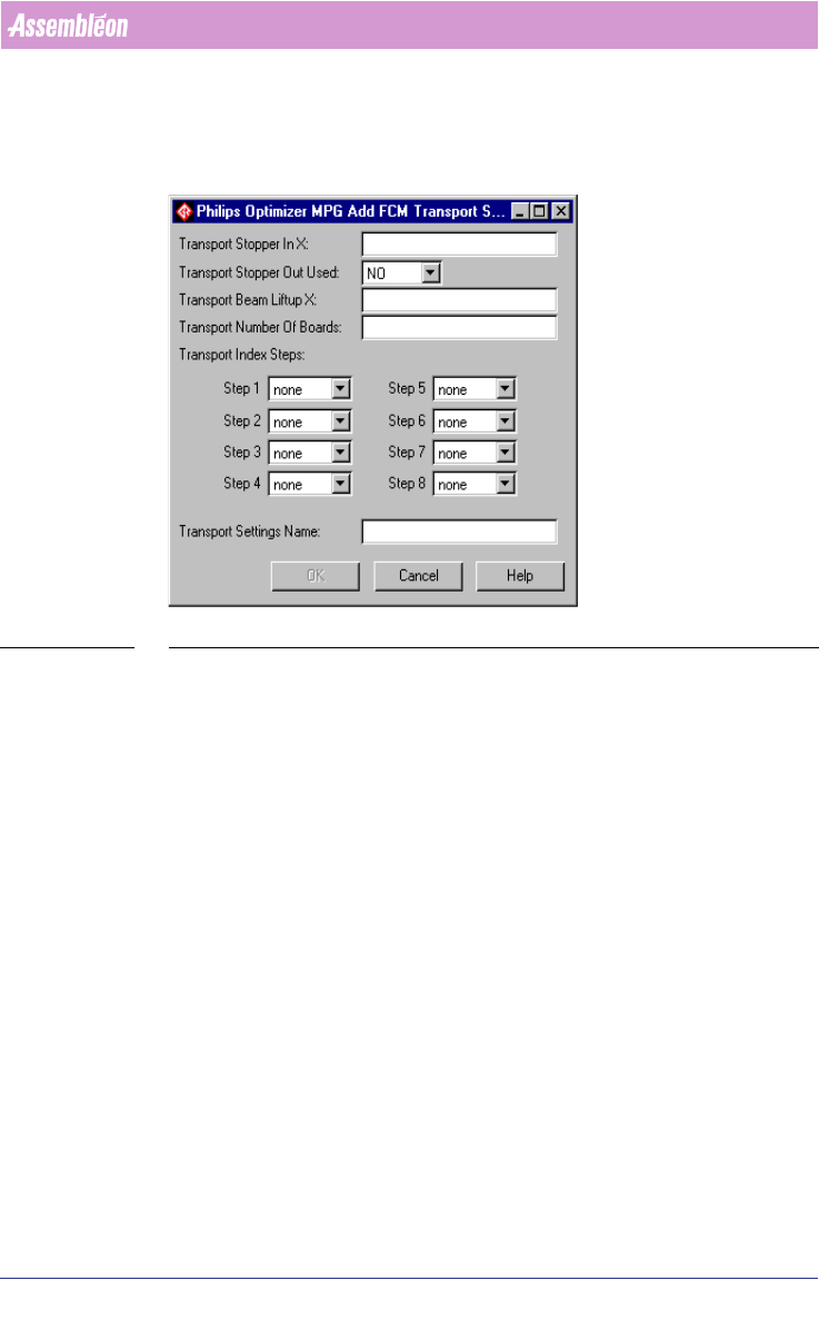
scheme must be filled in the Transport Settings Name textbox. After pressing
the OK button, the transport settings are added to the FCM Transport
Settings frame. The specified index scheme will be joined with the currently
specified machine in the Program Machine tab of PPS-Pro.
SCREEN 61 Add Transport Setting
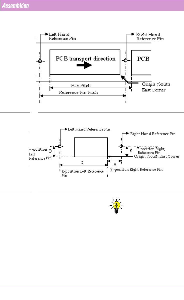
3.2.11.4 Reference Pins Positions
This paragraph describes the default values for the reference pin positions for
the FCM Multiflex machine.
Two reference pins are in use (out of 4 possible pins) namely the right hand
reference pin and the left hand reference pin. The co-ordinates (x,y) for right
and left hand reference pins must be specified in ‘mm’ and measured with
respect to the south-east corner of the PCB
(see SCREEN 62 on page 104).
Reference pin pitch is equal to the PCB pitch.
Refer to the manual “Description ALE-file 12NC 4022 591 98715” for infor-
mation on how to set this parameters.
User Manual 4022 591 98247
104 PPS-Pro v8.2 05.07
Guidelines for using PPS-Pro
SCREEN 62 Reference Pin Positions
SCREEN 63 Reference Pin Positions Measurement
NOTE: In most cases the DEFAULT for the right reference pin and left reference pin
will be enough to make correct placement programs.
But in cases non-defaults are wanted or needed there are different ways of
manipulate these settings.
There are four different situations to set these reference pin positions and
they are described below:
Situation 1: Multiflex Board Support (MBS)

4022 591 98247 User Manual
05.07 PPS-Pro v8.2 105
Guidelines for using PPS-Pro
In the example shown, see SCREEN 63 the right hand reference pin has co-
ordinates (A,B) mm. Default co-ordinates are (3.5,36.0) mm. Refer to the
Multiflex Board Support manual for more information.
Use the following formula to calculate left hand reference pin’s X co-ordinate:
x co-ordinate = A - PCB pitch
y co-ordinate = B
Situation 2: Carrier Set
On the carrier set, a sticker is provided for the indication of the reference pins
values at the right end of the carrier.
Situation 3: Carrier Kit
In the example shown, see SCREEN 63 the right hand reference pin is (A,B)
mm. Default co-ordinates are (3.5, 65.5) mm.
Deviation in Y direction is not possible.
Deviation in X direction is possible only in steps of 10mm because the holes
for the pins have a 10mm pitch. Use the following formula to calculate left
hand reference pin’s X co-ordinate:
x co-ordinate = A - PCB pitch
Situation 4: Customized Carrier Kit
Refer to situation 3.
The coordinates for the default location of the right-hand reference pin from
a "customized carrier" are (3.5, 56.0).
3.3 A-Series Guidelines for PPS-Pro
For information on ALE and PSI about the A-Series use the manuals
Description ALE-file (12nc 4022 591 98715) and the Description PSI-file
(12nc 4022 591 98815)
3.3.1 Automatic precedence relations for AX machines
This function can be activated for one ore more AX machines in the same line
by setting the following machine attribute in the ALE file:
EnableNeighborhoodRestrictions “TRUE”
During optimization the optimizer will check if the placements of smaller
parts in the vicinity of large parts could cause contact between nozzle shaft
and larger part. If this is the case, then the optimizer will reorder the actions
such that the larger part will be placed after the small part(s) that are nearby.
Note that if the line ends with an AQ machine that the parts will not auto
-
matically be moved to the AQ.