PPS Pro version 8.2 - 第126页
User Manual 4022 591 98247 122 PPS-Pro v8.2 05.07 Guidelines for using PPS-Pro 6. “ Nex t ”-button: If the corr ect artwork fidu cials are fo und via th e ‘extr act artwork’, this proc ess can be st opped by u sing th e …
4022 591 98247 User Manual
05.07 PPS-Pro v8.2 121
Guidelines for using PPS-Pro
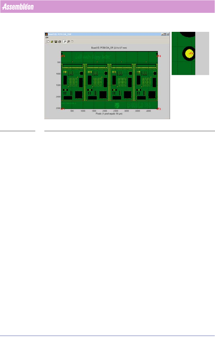
SCREEN 72 Aligned Artwork with board data
3.3.4.5 Preprocessing PCB data
Other options in the “Preprocessing PCB data”-window are: (see SCREEN 69
"Step2 Aligning artwork with Cad data" on page 119)
1. “Match fiducial with Copper”-frame: By activating the button “Automatic”
the matching between the MDF data and the Gerber data can be
performed.
2. “Match layer with Copper”-frame: By ticking and un-ticking, solder resist
layer can be shifted by using the “^v<>”-buttons. With these buttons the
selected layers can be shifted by the step size (in um)
3. “Edit layer”-frame: By ticking and un-ticking copper layer, solder resist
layer can be selected for deletion.
a) Delete:The deletion can be done via the “delete”-button.
b) Crop”: With this button the selected layers can be cropped.
Example: If the Gerber data also contains a frame or other non-
relevant data out-side of the PCB data, this can be cleaned.
4. Enable artwork types: When the AX doesn’t recognize the genetrated
Artwork it is possible to disable certain kind of Artworks
5. “Extract artwork”: (Note, this is currently not automatic) This will start
the artwork extraction. This will take some minutes. A progress bar is
shown and the “Next”-button is enabled
a) Only scan upper and lower regions: When there is not sufficient
Artwork in the upper and lower regions this option can be used
for extracting artwork in the middle of the board
User Manual 4022 591 98247
122 PPS-Pro v8.2 05.07
Guidelines for using PPS-Pro
6. “Next”-button: If the correct artwork fiducials are found via the ‘extract
artwork’, this process can be stopped by using the “Next”-button. All
windows of the artwork extraction will be closed and the Assembléon A-
Series optimizer will be started
(see 2.25.1.3 "Generate the production
program" on page 65). Note: The ‘Next’-button is greyed-out if the artwork
extraction is not completed.
7. “Exit”-button: This will aboard the optimizing process and no calculation
is started.
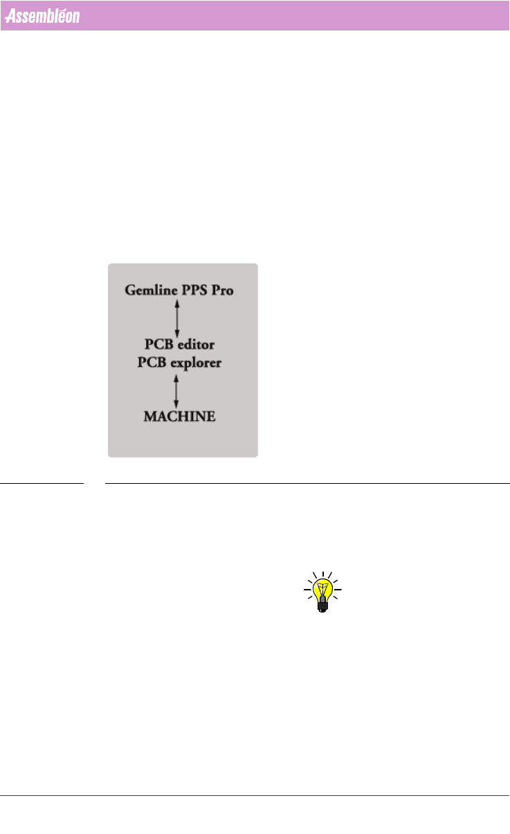
3.4 GemLine optimizer/generator Guidelines for PPS-Pro
This section describes how to use GemLine optimizer/generator.
FIGURE 12 Gemline PPS-Pro
For installation refer to the installation guide of Gemline PPS. Note that
GemLine opt/gen 8.0 is compatible with PPS-Pro 8.2.
For GemLine generator/optimizer and for its usage and proper installation
within PPS-Pro you need separate licences.
NOTE: When you install PPS-Pro, the permanent license keys for GemLine
optimizer/generator can be obtained from Assembléon,
support.software.emt@philips.com. When you have a temporary license, the
program will periodically remind you to register the program. So please
request the permanent license key to which you are entitled.
4022 591 98247 User Manual
05.07 PPS-Pro v8.2 123
Guidelines for using PPS-Pro
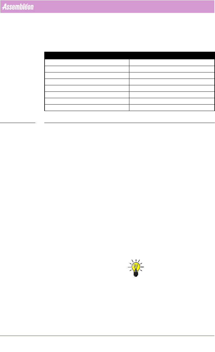
3.4.1 Synonyms
In the User Interface of GemLine optimizer/generator and of PPS-Pro different
synonyms are used.
TABLE 7 PPS-Pro vs. GemLine Pro Definitions
3.4.2 Machine definition
The machines need to be defined in both the ALE file of PPS-Pro and in
GemLine PPS. In the ALE file a general description of the machine is defined.
This is used during line distribution in PPS-Pro of mixed lines. In GemLine PPS
a much more detailed description of the machine is needed because it creates
a working program for specific machines.
More information on defining machines and lines in GemLine PPS can be
found in the GemLine PPS User Manual, Line and Machine setup. Information
on defining machines and lines in PPS-Pro can be found in the Description ALE
file document.
Before using the Gemline optimizer/generator note following guidelines:
■ The PCB origin definition in PPS-Pro is not used
■ Use the PPS-Pro import setting defaults to set the fixation method, see
3.4.11 on page 129.
■ By default the PCB origin in GemLine PPS is set at x=0.0, y=0.0 for each
PCB. Should an other setting be required use manual optimization.
In GemLine PPS, the machines are defined by using PCB explorer.
NOTE: The names of the machines defined in the line of GemLine PPS have to be
exactly the same as in the ALE-file. The machine names are case sensitive
and the GemLine machine names are restricted to 12 characters.
It is advised to define line 1 in PCB Explorer with all the GemLine machines
added to it (with a maximum of 10). Then it is possible to use the ALE editor
to create any combination of machines you want in a cell.
PPS-Pro definition GemLine PPS-Pro Definition
PanelFidMark PCBFiducial
BoardFidMark CircuitFiducial
PartFidMark ComponentFiducial
PanelBadMark PCBBadMark
BoardBadMark CircuitBadMark
Panel PCB
Board Circuit
Part Number Component