PPS Pro version 8.2 - 第140页
User Manual 4022 591 98247 136 PPS-Pro v8.2 05.07 Guidelines for using PPS-Pro 3.6 Specify FeederOff set The ‘ FeederOffset’ , which can be specified for ea ch in dividual feed er in the ALE file , expresses the n u mber…

4022 591 98247 User Manual
05.07 PPS-Pro v8.2 135
Guidelines for using PPS-Pro
3. After finishing the pre-assigned set-up, start the Data Optimizer >
Optimizer. Select the PCB PRO70_COMB from the PCB Setup files.
4. When needed edit this PCB setup. For example to use the static database
or use other special settings.
5. Now optimize PRO70_COMB.
6. After optimization save the result in the proposed file PRO70_COMB_RES
(so PPS-Pro can find it).
7. Select all the PCB’s to be optimized (for e.g. PRO70_PCB1, PRO70_PCB2
etc.,) and start optimization for these PCB’s.
8. After optimization finishes save all the results of PCBs with the proposed
PCB names, PRO70_PCB1_RES, PRO70_PCB2_RES etc.
9. Close the result window and close the PCB editor window.
10. The results of the optimization process are reported back to the PPS-Pro
application. PPS-Pro will now generate all required listings.
3.4.14.4 Feeder position - TopazXi
■ Description: The feeder bar for a TopazXi machine is defined as containing
40 positions (1-40). This information will be used by the run time
balancer during the allocation of feeders to feeder bar slots. The run time
balancer could assume that it is possible to allocate a 44 mm feeder to
positions 19 to 21. In reality the TopazXi has two feeder bars with 20
positions each, with a camera in between. It could be a problem if too
many large feeders are assigned to the TopazXi machine. The calculation
that takes place after line balancing will not be able to find a solution if it
gets too many parts
■ Advice: Re-allocate some components to other machines.
3.5 Set feeder inventory
To set limited resources for feeders on machines the inventory values in the
ALE file can be changed. Refer to manual Description ALE-file 12nc 4022 591
98715.
NOTE: Setting limited resources for feeders affects the optimizer result.
If the inventory is set to a limited value the optimizer is restricted to assign a
maximum number of the specified feeder type. This may affect the quality
(output) of the calculated results.
Setting limitless resources for feeders can be done in two ways.
1. Set the value in the Inventory field to ‘1000’.
2. Omit the Inventory field for feeders entirely.
User Manual 4022 591 98247
136 PPS-Pro v8.2 05.07
Guidelines for using PPS-Pro
3.6 Specify FeederOffset
The ‘FeederOffset’, which can be specified for each individual feeder in the
ALE file, expresses the number of slots away a feeder must be placed from a
specified feeder. This value measures the slots between the feeders’ address
slots (the address slot is the slot among those consumed that is plugged into
the bank). Information on offsets for your feeders is described in your
machines documentation. Refer to that documentation to set up FeederOffsets
in the ALE file. The ‘FeederOffset’ is only used by the ‘Line Scheduler’, ‘Board
Scheduler’ and ‘Runtime Balancer’. The Assembléon optimizers do not use this
value. Instead exact dimensions, which are provided by means of initial data
tables, are used.
NOTE: When FeederOffset statements are used, the ‘Slots’ and ‘AddrSlot’
statements are ignored. The ‘FeederOffset’ can play a significant role when
a line is specified which contains some different machine types.
3.7 Pre-assign Feeders
Every PCB calculation results in a number of .con files (one per machine in the
line). A.con file contains information on the feeder setup of machines for the
calculated PCB (among other information).
It is possible to use the .con files that belong to current machine configu-
rations as input for a new PCB calculation. This ensures that the same setup
can be used for both PCBs. This leads to a considerable decrease of the change
over time.
An important rule is that the .con file that a user wishes to re-use as input
has to be copied to another directory since a new calculation will overwrite it.
In principle .con files have to match the flowlines (see FIGURE 13 on page
137). It is not advised to use .con files for flowlines with different setups/
layouts unless the user is sure that there will not be any incompliancy.
It is not possible to use .con files when the feederbars have not been fixed
(meaning they have to be specified in the ALE file when a pre-assignment is
applied).
4022 591 98247 User Manual
05.07 PPS-Pro v8.2 137
Guidelines for using PPS-Pro
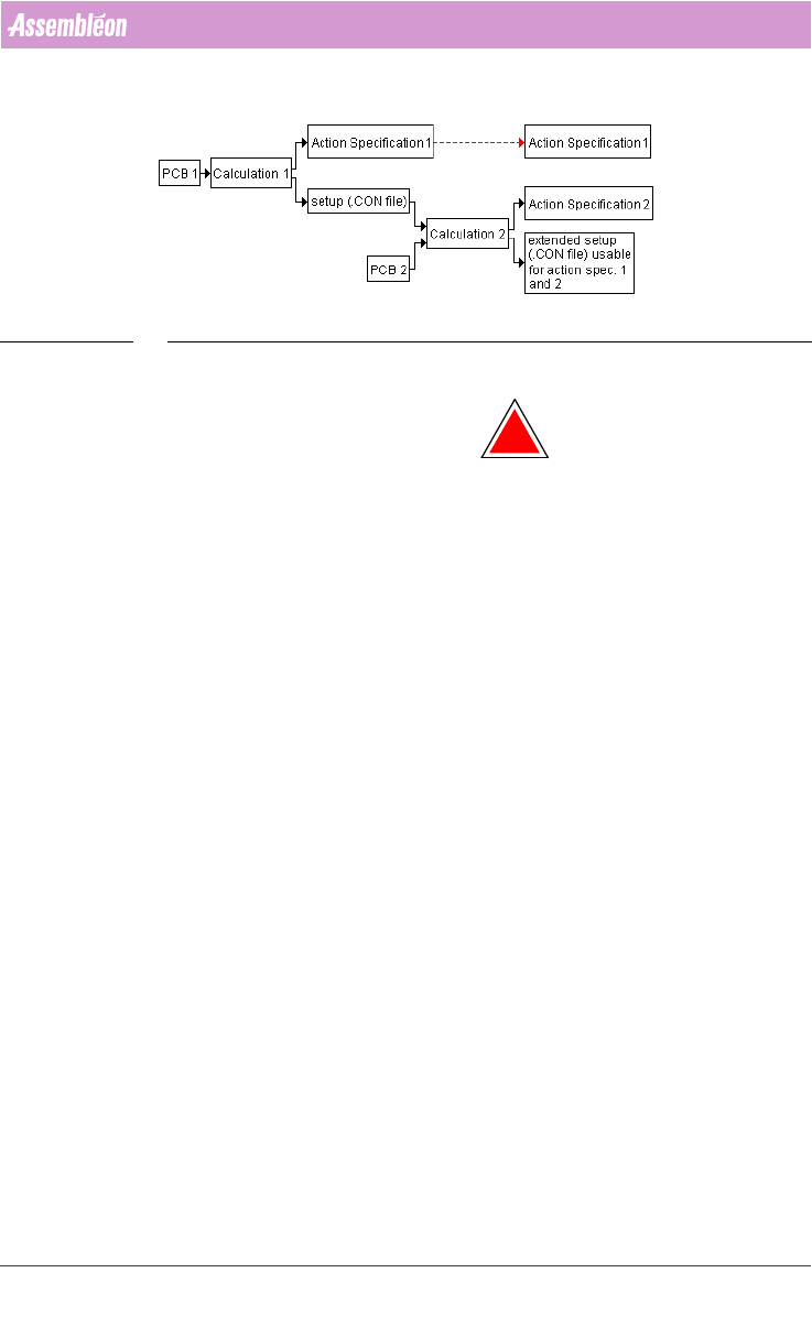
FIGURE 13 Workflow Pre-assignment
Action specification 1 can also be used with the extended setup.
!
WARNING: It is likely that PCB 1 contains parts that are not in PCB 2. In this case,
ensure that the parts that are in PCB 1 and not in PCB 2 are present in the
PSI file that is used for the calculation. Otherwise the .con file resulting
from calculation 2 will not contain all setup information.
In general, PCB 2 is a newer version of PCB1. This method works most effi-
ciently if changes are small.
The .con files can also be used to pre-assign nozzles to heads on machines.
3.7.1 Modification of older PSI files
In some older PSI files (Version 6.0 and 6.1) this field is named
‘Philips_AlternatPos’ instead of ‘Philips_AlternatePos’ If the PSI file contains
this error, it is necessary to correct it. This can be achieved by following the
instructions below.
1. Start the Part Information Manager (PIM).
2. Select the Types tab.
3. For all types shown (*, C, CR, J, PackageDesc,...) select the field
‘Philips_AlternatPos’ and change it to Philips_AlternatePos’. To change the
name of a selected field click the Rename button. After all modifications
have been done, save the file.
The procedure that needs to be followed in order to obtain alternate feeding
depends on the type of feeder. Below, the procedure is described for tape,
stick and tray.
3.7.2 Alternate feeding with tape feeders (ACM)
Start PIM and select the part or package that requires alternate feeding.
Select the field ‘Philips_AlternatePos’ and set its value to ‘YES’.