PPS Pro version 8.2 - 第165页
4022 591 98 247 U ser Manual 05.07 P PS-Pro v8.2 161 Guidelines for using PPS-Pro Follow i ng p i ct u re g i ves a n ove r vi ew of t he se m ach in es ty p es : FIGU RE 16 ACM ma chine di agram T op vi ew A.5.3.3 Modul…

User Manual 4022 591 98247
160 PPS-Pro v8.2 05.07
Guidelines for using PPS-Pro
A.5.3.2 Feederbar Configuration
The maximum amount of feederbars these machines can have is 4 (double
sided ACM; Feederbar 1-4). An AQ-1-module and D9 machine are always single
sided, thus have 2 feederbars (1 and 2).
For the ACM and D9 machine this feederbar can either be a:
FeederTrolley - A moveable feederbar with 25 slots on which a maximum of
25 8mm tapes fit (ITF2_08).
FeederBank1 - A fixed feederbar with 25 slots on which a maximum of 25
8mm tapes fit (ITF2_08).
TrayTrolley1 - A moveable feederbar which has 50 pallets. In each pallet a
maximum of 2 trays can be defined.
TrayPallet1 - A fixed feederbar which has 1 pallet. In this pallet a maximum of
2 trays can be defined.
For the AQ-1 this can either be an ACM_Feeder_Bank, ACM_Feeder_Trolley,
ACM_Tray_Pallet or ACM_Tray_ Trolley.
ACM_Feeder_Trolley - A moveable feederbar with 25 slots on which a
maximum of 25 8mm tapes fit (ITF2_08).
ACM_Feeder_Bank - A fixed feederbar with 25 slots on which a maximum of
25 8mm tapes fit (ITF2_08).
ACM_Tray_Trolley - A tray trolley which has 48 pallets. In PPS on each pallet a
maximum of 2 trays can be defined.
ACM_Tray_Pallet - A fixed pallet. In PPS a maximum of 2 trays can be defined
on it.
4022 591 98247 User Manual
05.07 PPS-Pro v8.2 161
Guidelines for using PPS-Pro
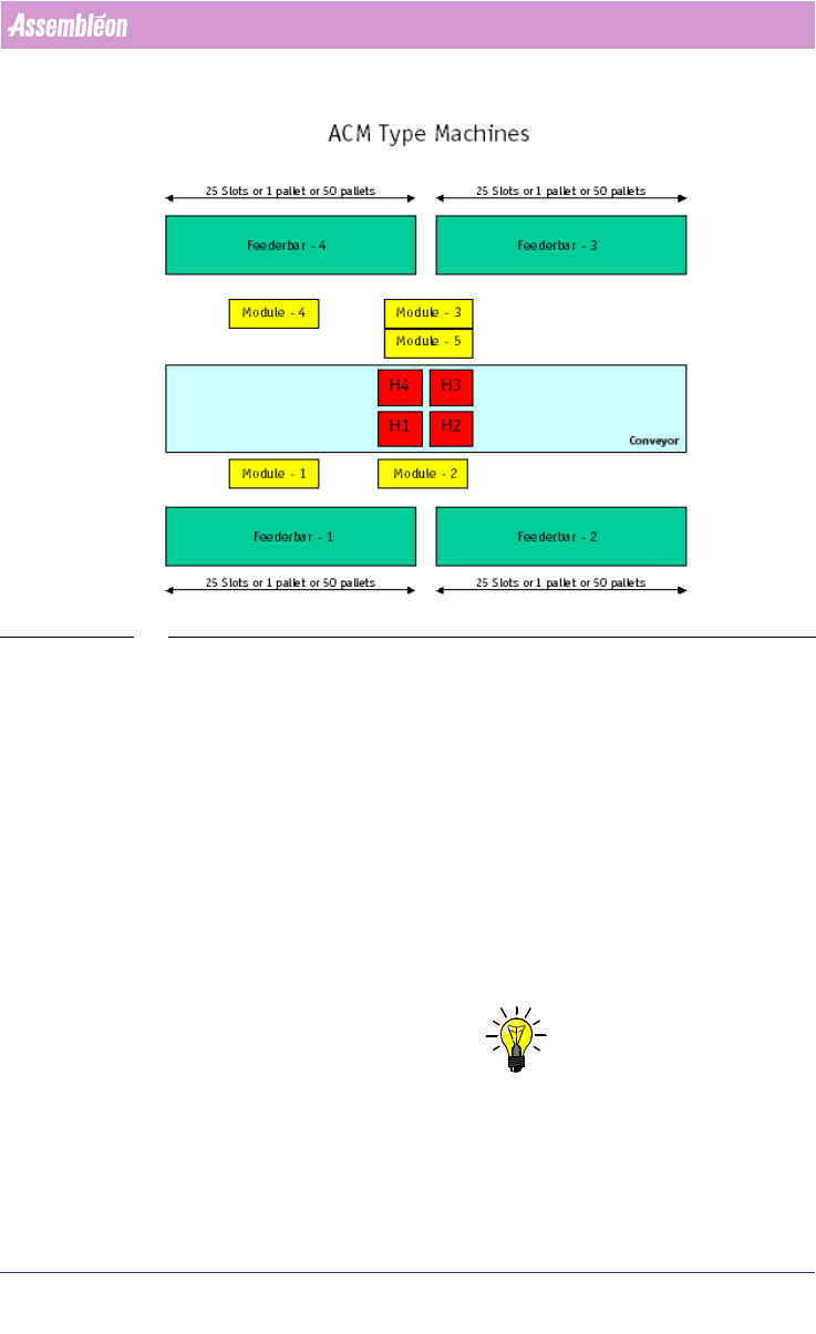
Following picture gives an overview of these machines types:
FIGURE 16 ACM machine diagram Top view
A.5.3.3 Module Positions
The machines have 5 Module positions. In these modules the following units
can be placed:
■ Module-1: Flux Unit or Toolbit Exchange Unit
■ Module-2: Chip Scale Package Camera or Fine Pitch Package Camera
■ Module-3: Chip Scale Package Camera or Fine Pitch Package Camera
■ Module-4: Toolbit Exchange Unit
■ Module-5: Flux Unit
Following restrictions apply to these modules:
■ When on Module-5 a Flux Unit is defined, then Module-3 MUST contain a
Chip Scale Package Camera!
NOTE: Refer to the OFI parameters for these modules (see A.6 "Machine OFI
Parameters" on page 162) .

User Manual 4022 591 98247
162 PPS-Pro v8.2 05.07
Guidelines for using PPS-Pro
A.5.3.4 Head Versus Feederbar Positions
In case the feederbars are of the type ‘FeederBank’ or ‘FeederTrolley’ then the
head reach to the feederbar pick positions is as followes:
Head-1: Feederbar-1: Position 1-25– Feederbar-2: Position 1-11
Head-2: Feederbar-1: Position 14-25– Feederbar-2: Position 1-25
Head-3: Feederbar-3: Position 1-25– Feederbar-4: Position 1-11
Head-4: Feederbar-3: Position 14-25– Feederbar-4: Position 1-25
In case the feederbars are of the type ‘Tray’ then the head reach (e.g. Head-1
to a Tray pallet on Feederbank2) depends on the size of the tray!
Explanation of picture: ACM Type Machines:
■ H1: Head 1
■ H2: Head 2
■ H3: Head 3
■ H4: Head 4
■ Feederbar – 1, 2, 3 and 4:
For the ACM and D9 machine this can either be a FeederTrolley, FeederBank1,
TrayTrolley1 or Tray Pallet1. For the AQ-1-Module this can either be an
ACM_Feeder_Bank, ACM_Feeder_Trolley, ACM_Tray_ Pallet or
ACM_Tray_Trolley.
A.6 Machine OFI Parameters
Each machine type requires an additional set of parameters in the OFI files.
This paragraph gives an overview of these parameters.
A.6.1 Machine Model Names
The OFI files require a for each machine type a model name. Some of the
machines require besides the model name a ModelType name as identifier. The
following model names/types are used:
TABLE 26 Machine type Model Relation
Machine Type Model ModelType
FCM-II FCM
FCM-IIM FCM MultiFlex
FCM-IIXM FCM MultiFlex_Extended
ACM ACM
D9 ACM
AQ-1 AQ
AX AX