PPS Pro version 8.2 - 第166页
User Manual 4022 591 98247 162 PPS-Pro v8.2 05.07 Guidelines for using PPS-Pro A.5.3.4 Head V ersus F eederbar Positions In case the feederbars are o f the type ‘ Fee de rB an k ’ or ‘ Fee de rTro ll e y ’ then th e hea …
4022 591 98247 User Manual
05.07 PPS-Pro v8.2 161
Guidelines for using PPS-Pro
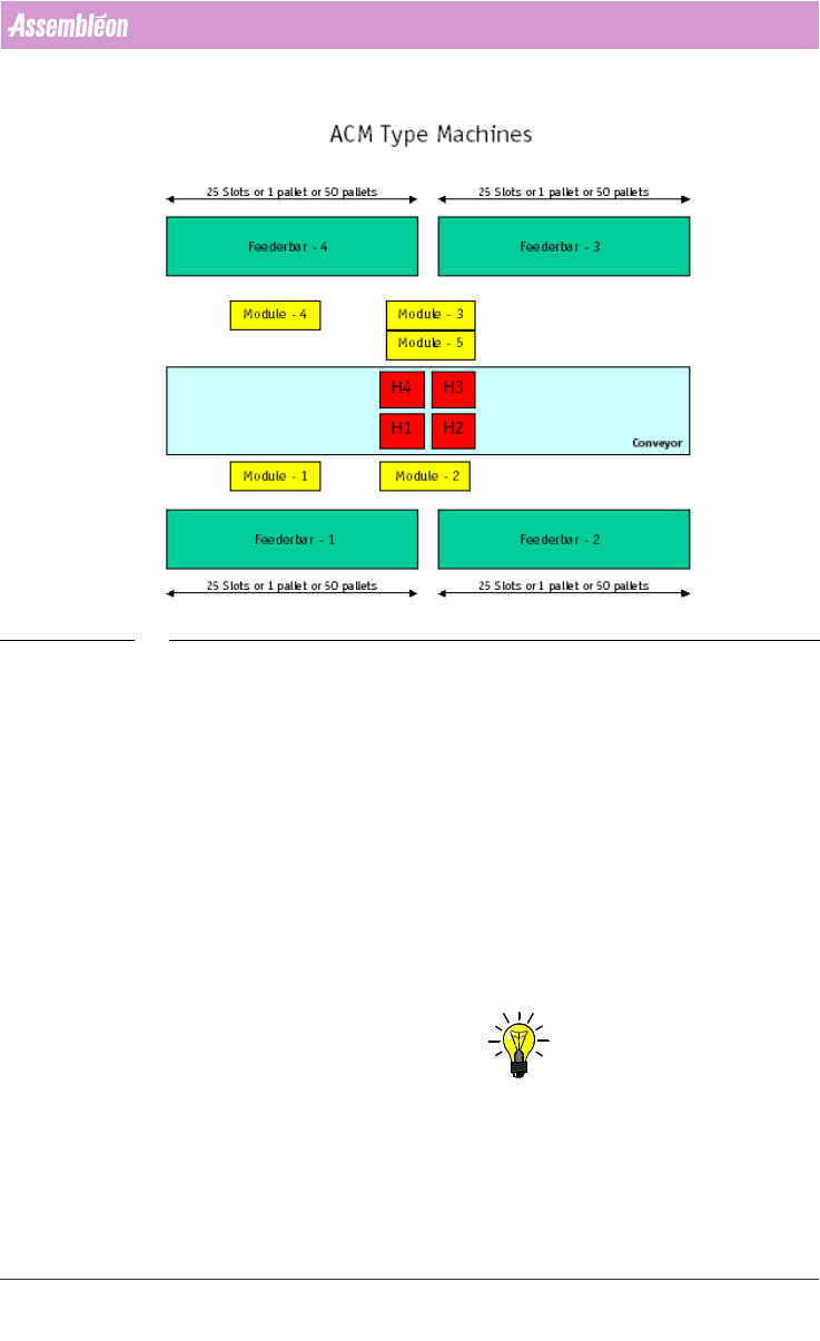
Following picture gives an overview of these machines types:
FIGURE 16 ACM machine diagram Top view
A.5.3.3 Module Positions
The machines have 5 Module positions. In these modules the following units
can be placed:
■ Module-1: Flux Unit or Toolbit Exchange Unit
■ Module-2: Chip Scale Package Camera or Fine Pitch Package Camera
■ Module-3: Chip Scale Package Camera or Fine Pitch Package Camera
■ Module-4: Toolbit Exchange Unit
■ Module-5: Flux Unit
Following restrictions apply to these modules:
■ When on Module-5 a Flux Unit is defined, then Module-3 MUST contain a
Chip Scale Package Camera!
NOTE: Refer to the OFI parameters for these modules (see A.6 "Machine OFI
Parameters" on page 162) .

User Manual 4022 591 98247
162 PPS-Pro v8.2 05.07
Guidelines for using PPS-Pro
A.5.3.4 Head Versus Feederbar Positions
In case the feederbars are of the type ‘FeederBank’ or ‘FeederTrolley’ then the
head reach to the feederbar pick positions is as followes:
Head-1: Feederbar-1: Position 1-25– Feederbar-2: Position 1-11
Head-2: Feederbar-1: Position 14-25– Feederbar-2: Position 1-25
Head-3: Feederbar-3: Position 1-25– Feederbar-4: Position 1-11
Head-4: Feederbar-3: Position 14-25– Feederbar-4: Position 1-25
In case the feederbars are of the type ‘Tray’ then the head reach (e.g. Head-1
to a Tray pallet on Feederbank2) depends on the size of the tray!
Explanation of picture: ACM Type Machines:
■ H1: Head 1
■ H2: Head 2
■ H3: Head 3
■ H4: Head 4
■ Feederbar – 1, 2, 3 and 4:
For the ACM and D9 machine this can either be a FeederTrolley, FeederBank1,
TrayTrolley1 or Tray Pallet1. For the AQ-1-Module this can either be an
ACM_Feeder_Bank, ACM_Feeder_Trolley, ACM_Tray_ Pallet or
ACM_Tray_Trolley.
A.6 Machine OFI Parameters
Each machine type requires an additional set of parameters in the OFI files.
This paragraph gives an overview of these parameters.
A.6.1 Machine Model Names
The OFI files require a for each machine type a model name. Some of the
machines require besides the model name a ModelType name as identifier. The
following model names/types are used:
TABLE 26 Machine type Model Relation
Machine Type Model ModelType
FCM-II FCM
FCM-IIM FCM MultiFlex
FCM-IIXM FCM MultiFlex_Extended
ACM ACM
D9 ACM
AQ-1 AQ
AX AX

4022 591 98247 User Manual
05.07 PPS-Pro v8.2 163
Guidelines for using PPS-Pro
A.6.2 Software Versions
Following is an overview of supported Program Formats by the optimizer:
TABLE 27 Program format for each machine type
A.6.3 Machine Specific Parameters
Per machine type, the following parameters can/have to be specified.
A.6.3.1 FCM Index Schemes
For the FCM type machines, the optimizer will calculate the required index
scheme (transport index settings). However, a user should be able to override
this by defining his own required index schema.
For FCM-II, FCM-IIM and FCM-IIXM machines, following parameters should be
user definable:
TABLE 28 ALE Settings Attributes for FCM-II, FCM-IIM and FCM-IIXM
Machine Type ProgramFormat
FCM-II 3 or 4
FCM-IIM 3 or 4
FCM-IIXM 3 or 4
ACM 3 or 4
D9 4
AQ-1 4
AX 1.11A, 1.10
Index Scheme Parameter FCM-II - FCM-IIM - FCM-IIXM
TransportStopperInX e.g.: -171
TransportStopperOutUsed YES or NO
TransportBeamLiftupX e.g.: -440
TransportNrOfBoards Number of boards, e.g.: 10
TransportIndexStep Up to 10 values. Allowed step
size 0 - 480, e.g.: 80 80 80