PPS Pro version 8.2 - 第167页
4022 591 98 247 U ser Manual 05.07 P PS-Pro v8.2 163 Guidelines for using PPS-Pro A.6.2 Softwar e V e rsions Follow in g i s a n ove rv i ew of su pp or t ed Program F ormats by the op t im i ze r: T ABLE 27 Prog ram f o…

User Manual 4022 591 98247
162 PPS-Pro v8.2 05.07
Guidelines for using PPS-Pro
A.5.3.4 Head Versus Feederbar Positions
In case the feederbars are of the type ‘FeederBank’ or ‘FeederTrolley’ then the
head reach to the feederbar pick positions is as followes:
Head-1: Feederbar-1: Position 1-25– Feederbar-2: Position 1-11
Head-2: Feederbar-1: Position 14-25– Feederbar-2: Position 1-25
Head-3: Feederbar-3: Position 1-25– Feederbar-4: Position 1-11
Head-4: Feederbar-3: Position 14-25– Feederbar-4: Position 1-25
In case the feederbars are of the type ‘Tray’ then the head reach (e.g. Head-1
to a Tray pallet on Feederbank2) depends on the size of the tray!
Explanation of picture: ACM Type Machines:
■ H1: Head 1
■ H2: Head 2
■ H3: Head 3
■ H4: Head 4
■ Feederbar – 1, 2, 3 and 4:
For the ACM and D9 machine this can either be a FeederTrolley, FeederBank1,
TrayTrolley1 or Tray Pallet1. For the AQ-1-Module this can either be an
ACM_Feeder_Bank, ACM_Feeder_Trolley, ACM_Tray_ Pallet or
ACM_Tray_Trolley.
A.6 Machine OFI Parameters
Each machine type requires an additional set of parameters in the OFI files.
This paragraph gives an overview of these parameters.
A.6.1 Machine Model Names
The OFI files require a for each machine type a model name. Some of the
machines require besides the model name a ModelType name as identifier. The
following model names/types are used:
TABLE 26 Machine type Model Relation
Machine Type Model ModelType
FCM-II FCM
FCM-IIM FCM MultiFlex
FCM-IIXM FCM MultiFlex_Extended
ACM ACM
D9 ACM
AQ-1 AQ
AX AX
4022 591 98247 User Manual
05.07 PPS-Pro v8.2 163
Guidelines for using PPS-Pro
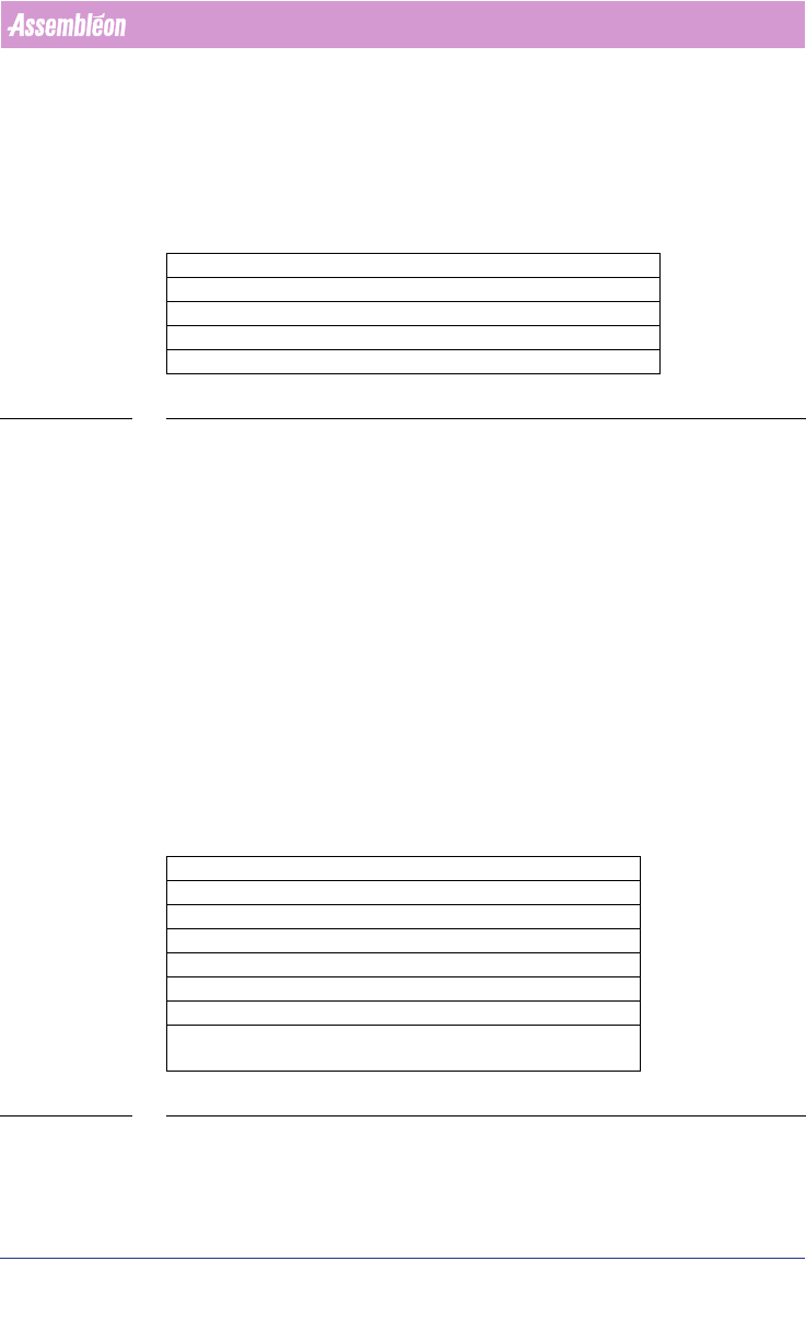
A.6.2 Software Versions
Following is an overview of supported Program Formats by the optimizer:
TABLE 27 Program format for each machine type
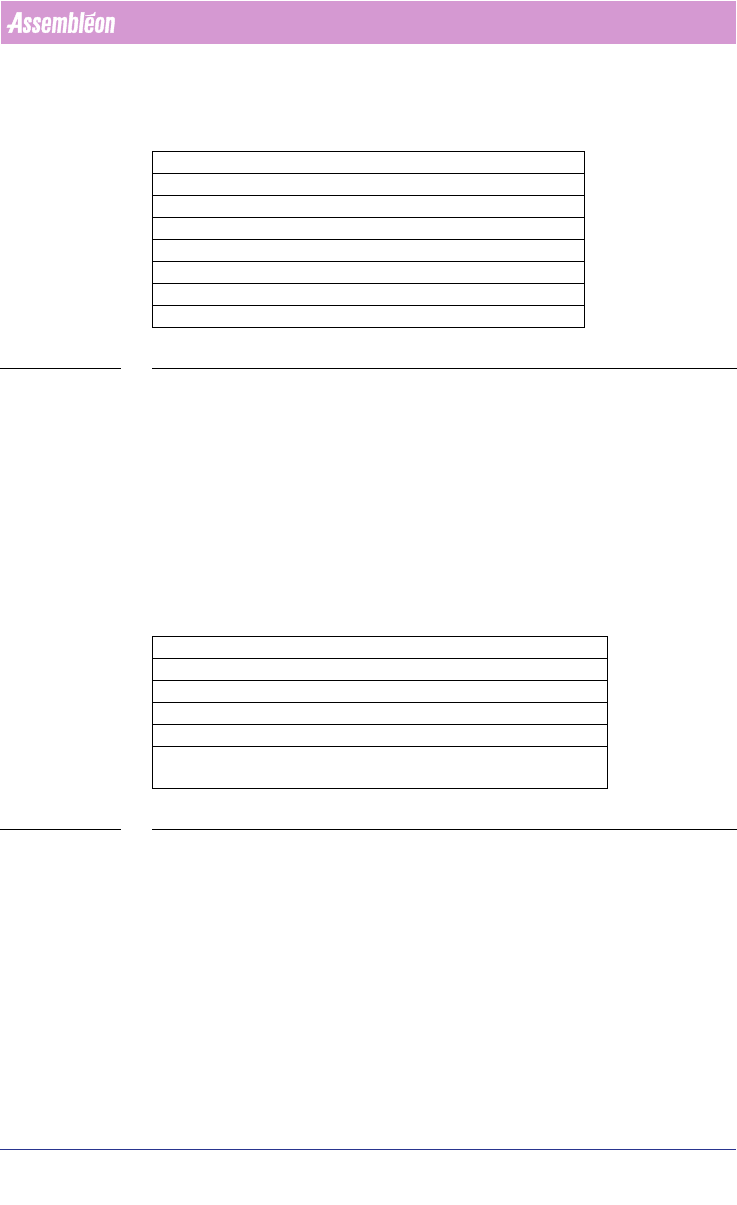
A.6.3 Machine Specific Parameters
Per machine type, the following parameters can/have to be specified.
A.6.3.1 FCM Index Schemes
For the FCM type machines, the optimizer will calculate the required index
scheme (transport index settings). However, a user should be able to override
this by defining his own required index schema.
For FCM-II, FCM-IIM and FCM-IIXM machines, following parameters should be
user definable:
TABLE 28 ALE Settings Attributes for FCM-II, FCM-IIM and FCM-IIXM
Machine Type ProgramFormat
FCM-II 3 or 4
FCM-IIM 3 or 4
FCM-IIXM 3 or 4
ACM 3 or 4
D9 4
AQ-1 4
AX 1.11A, 1.10
Index Scheme Parameter FCM-II - FCM-IIM - FCM-IIXM
TransportStopperInX e.g.: -171
TransportStopperOutUsed YES or NO
TransportBeamLiftupX e.g.: -440
TransportNrOfBoards Number of boards, e.g.: 10
TransportIndexStep Up to 10 values. Allowed step
size 0 - 480, e.g.: 80 80 80
User Manual 4022 591 98247
164 PPS-Pro v8.2 05.07
Guidelines for using PPS-Pro
A.6.3.2 AX Index Schemes
For the AX type machines, the optimizer will calculate the required index
scheme (transport index settings). However, a user can override this by
defining his own required index schema.
For AX machines, following parameters can be modified:
TABLE 29 ALE Settings Attributes for AX
For the conveyor settings there are 3 possible options:
■ Auto mode
■ Semi-Auto mode
■ Manual mode
Normally use Auto mode. This means that NONE of following AX machine
production parameters are entered in the ALE file: TransportStopperInX,
TransportNrOfBoards, TransportIndexStep, TransportPanelPitch.
There might be situations you want to use Semi-Auto or Manual mode. This is
however not advised! For Semi-Auto the production parameters Transport
-
StopperInX and TransportPanelPitch must be specified in ALE. For Manual-
Auto the production parameters TransportStopperInX, TransportNrOf
-
Boards, and TransportIndexStep must be specified in ALE.
A.6.3.3 FCM-II – FCM-IIM – FCM-IIXM Production Parameters
For these machines the following parameters can be changed:
TABLE 30 ALE Settings Attributes for FCM-II, FCM-IIM and FCM-IIXM
The Mark parameters refer to the used shape definition file (vision file) on the
FCM machines.
Index Scheme Parameter AX
TransportStopperInX e.g. 0.036 (unit is meters!)
TransportNrOfBoards e.g. 24
TransportIndexStep e.g. 0 0.12 (unit is meters!)
TransportPanelPitch e.g. 0.12 0.12 (unit is meters!)
Parameter FCM-II - FCM-IIM - FCM-IIXM
BoardVision BMS+DFA or BMS or DFA or NO
BVM1Index YES or NO
PanelFidMark <number 1 – 255> e.g.: 1
BoardFidMark <number 1 – 255> e.g.: 2
PanelBadMark <number 1 – 255> e.g.: 3
BoardBadMark <number 1 – 255> e.g.: 4
VisionPosition 1 or 2 or 3 - For a WPM head this param-
eter has to be defined