PPS Pro version 8.2 - 第171页
4022 591 98 247 U ser Manual 05.07 P PS-Pro v8.2 167 Guidelines for using PPS-Pro T ABLE 33 ALE Settings Attribut es for A CM, AQ -1, D-9 The Mark param eters r efer to th e us ed shape d efinition file (vision fil e) on…

User Manual 4022 591 98247
166 PPS-Pro v8.2 05.07
Guidelines for using PPS-Pro
third 3. This information is used when parts have to be placed last, these are
transferred to the machine with the highest LogicalPositionInLine.
PanelFidMark, BoardFidMark, PartFidMark fields: When the used fiducials,
either in LAR- or DSF ProductionMode have no name assigned, then this user
definable name will be used in the Placement Program. This name refers to
the used shape definition file (vision file) on the AX machines.
BadMarkId field: Specifies the name that has been assigned in the MDF file
(CAD) file for the badmark.
The DoNotDuplicatePreassignments field: When preassigned parts are not
allowed to be duplicated this option can be used. Note that parts in the PCB
should be reachable (and the fiducials should be read in advance), otherwise
this option should be turned off.
The AlignmentMatrixPerCircuit field: Only the fiducials in the circuit itself may
be used for alignment of the parts in the circuit. (Important when carriers are
used.)
The MaximumNoFiducialsPerAlignmentMatrix field: This field defines the
number of fiducials that will be scanned per Alignment Matrix.
The BadmarksRequireFiducials field: This field specifies if it is mandatory to
first read fiducials before badmarks can be read, or not. (Practical situation is
circuit carriers without fiducials.)
The EnableNeighborhoodRestrictions field: This field specifies if the optimizer
for AX machines has to take care that the placement of smaller parts next to
larger parts can cause the nozzle shaft to displace the larger parts. By turning
on this function the optimizer will generate programs where the larger parts
will be placed after the small parts that are nearby have been placed.
The ProductionDirection field: Can only be used if special hardware modifi-
cations have been done on the machine in order to allow PCB transport in
reverse direction.
NOTE: See for the other parameters the ALE Description.
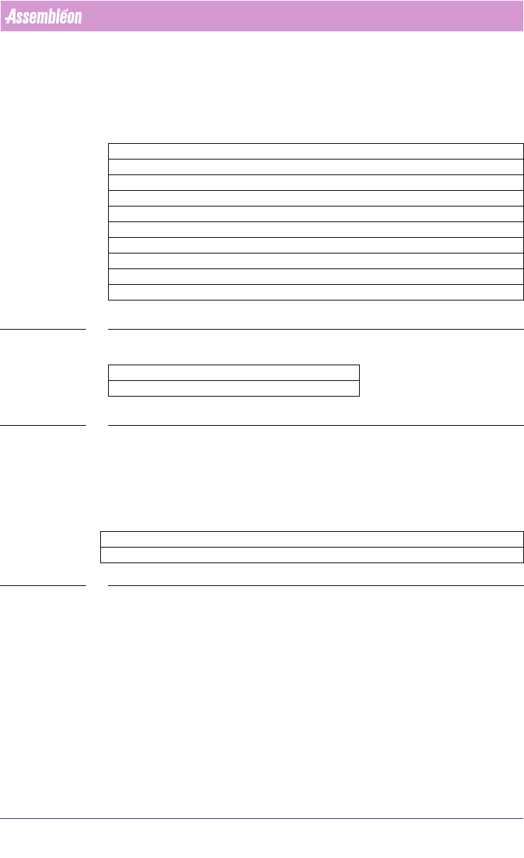
A.6.3.5 ACM, AQ-1 and D9 Production Parameters
For these machines the following parameters can be set:
Parameter ACM – AQ-1, AQ-2 – D9
ModulePosition1 FLUX or TEU
ModulePosition2 CSP, FP (AQ1)
or
DV_SFOV, DV_LFOV (AQ2)
4022 591 98247 User Manual
05.07 PPS-Pro v8.2 167
Guidelines for using PPS-Pro
TABLE 33 ALE Settings Attributes for ACM, AQ-1, D-9
The Mark parameters refer to the used shape definition file (vision file) on
these machines.
NOTE: When a module position is not defined by the user then it is not used.
(Affects PlaceLast functionality)
ModulePosition3 CSP, FP (AQ1)
or
DV_SFOV, DV_LFOV (AQ2)
ModulePosition4 COPLANARITY or TEU
ModulePosition5 FLUX
PanelFidMark User definable vision filename on machine, e.g.: CIRCLE
BoardFidMark User definable vision filename on machine, e.g.: CIRCLE
PartFidMark User definable vision filename on machine, e.g.: CIRCLE
PanelBadMark User definable vision filename on machine, e.g.: SQUARE
BoardBadMark User definable vision filename on machine, e.g.: SQUARE
User Manual 4022 591 98247
168 PPS-Pro v8.2 05.07
Guidelines for using PPS-Pro
A.6.3.6 ACM, D9, AQ-1 and AQ-2 Tray Definitions
A user can define his own trays, including name and all required dimensions.
These new user trays should then be selectable on the required Tray-pallets.
The following parameters define a Tray:
TABLE 34 ALE Settings Tray for ACM, AQ-1, D9
For the AQ-1, the following parameter can be set:
TABLE 35 ALE settings AQ-1, AQ-2
Refer to AX machine Production Parameters for an explanation regarding this
parameter.
A.6.3.7 Optimizer Names
The following is a list of Assembléon optimizer names.
TABLE 36 Machine Optimizer to be used
Parameter ACM – AQ-1 – D9 Definable TRAYS
XDimension X-size of tray, e.g.: 135.9
YDimension Y-size of tray, e.g.: 322.6
ZDimension Z-size of tray, e.g.: 12.19
XPick X-Center location first part in tray, e.g.: 17.7
YPick Y-Center location first part in tray, e.g.: -22.7
XNr Number of ‘cells’, e.g.: 5
YNr Number of ‘Rows’, e.g.: 11
XPitch X-distance between 2 ‘Cells’, e.g.: 25.1
YPitch X-distance between 2 ‘Rows’, e.g.: 27.7
Parameter AQ-1, AQ-2
LogicalPositionInLine 1 or 2 or 3 etc
Parameter FCM-II FCM-IIM FCM-IIXM ACM D9 AQ-1, AQ-2 AX
OptimizerName Emt_mod.exe AssembleonOptimizer.bat