PPS Pro version 8.2 - 第33页
4022 591 98 247 User Manual 05.07 PPS-Pro v8.2 29 PPS-Pro GUI Rem ove_shapes: <packa ge-name> Pins_fr om_PSI: * Fiducial s: <packa ge name which has to be regar ded as fiduc ial> Alias: master string1 When im…
User Manual 4022 591 98247
28 PPS-Pro v8.2 05.07
PPS-Pro GUI
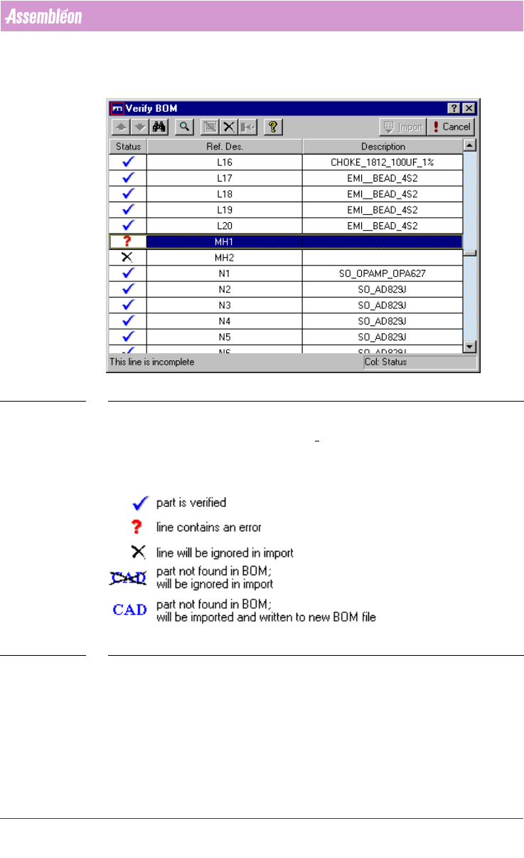
between your BOM-file and the product, or between the BOM-file and the
selected BOM-format. To complete the BOM import, all parts must be verified.
SCREEN 20 Verify BOM file
When all the parts are imported with the status “Part is verified” (see SCREEN
21 on page 28) -Blue tick, then the Import tab is activated and ready for
importing.
SCREEN 21 Verify Status legend
Press the Import button in the Verify BOM window
2.9 Cad override
With CAD override files it is possible to obtain automatic changes during the
CAD import process. The following cad overrides can be convenient:
4022 591 98247 User Manual
05.07 PPS-Pro v8.2 29
PPS-Pro GUI
Remove_shapes: <package-name>
Pins_from_PSI: *
Fiducials: <package name which has to be regarded
as fiducial>
Alias: master string1
When importing ‘SmartCAD’ or ‘GenCAD’ files all packages that are not present
in the PSI file will automatically be classified as through-hole components in
the resulting MDF file. Users who only work with SMD equipment do generally
not want this behaviour. Automatic definition as SMD part is obtained by
invoking a CAD override file containing the following line:
SMD_part: *
For more details refer to the online help on cad overrides with ‘SmartCAD’ or
‘GenCAD’ import. If the importing took already place and the MDF file contains
a number of SMD parts classified as through hole, then it is adviced to add the
parts to PSI, delete the MDF and re-import again.
The Alias command provides a possibility to convert unknown package names
from the input file into known names as specified in PSI. For a detailed
description refer to the manual “Description PSI 8.2”, chapter 2.
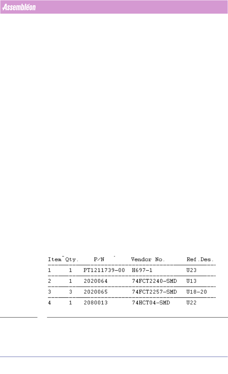
2.10 How to use a BOM file
BOM (Bill Of Materials) files are text-files that contain reference designators,
Vendor names and possibly even more component information
(see FIGURE 1
on page 29). With a BOM-file it is possible to select components from CAD-
data, or update component information in an MDF-file. A BOM-file is useful
when panels, which are quite similar but do not carry exactly the same
components (so-called family-boards) are produced. All panels will be using
the same board-design/cad-data, but each product has its own BOM-file to
specify which components should be mounted and which should not be
mounted.
FIGURE 1 BOM file - Example
User Manual 4022 591 98247
30 PPS-Pro v8.2 05.07
PPS-Pro GUI
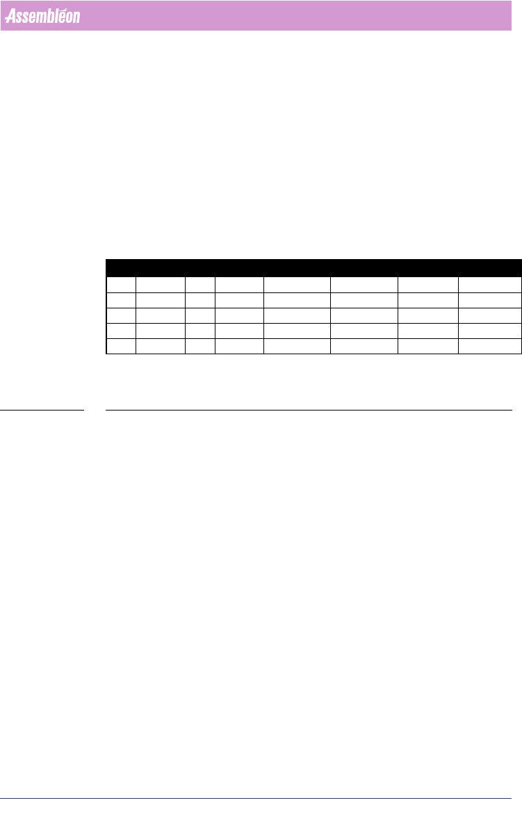
2.11 Difference between “normal” and “strict” BOM
import
■ Normal (see TABLE 2 on page 30):
All components which are present in the CAD-file, are also present in the
MDF-file after importing the BOM-file. Only the component information which
is available in the BOM-file is changed in the created MDF-file.
■ Strict (see TABLE 2 on page 30):
Only components which are present in the BOM-file are present in the MDF-
file after importing the BOM-file. The component information of the BOM-file
is used in the created MDF-file.
C = Component
VN = Vendor number (component info.)
TABLE 2 Principle of normal and strict BOM import
2.11.1 Import via the Import BOM tab
Sometimes a BOM file will be received (long) after a project has been set up,
or a new BOM-file must be imported. When this happens, open the existing
project and use the Import BOM tab to bring in the new BOM.
The procedure for importing a BOM-file via the Import BOM tab is analogue to
the procedure for ‘normal’ importing via the Import Data tab. The only
difference is the startup of the ‘BOM-Formats Explorer’.
To start the ‘BOM-Formats Explorer’, the following steps must be taken (see
SCREEN 22 on page 31):
■ Select the Import BOM tab
■ Press the Browse... button and browse to the BOM-file
■ Press the Formats... button to startup the ‘BOM-Formats Explorer’ and
select the correct format from the list. If no correct format is available, a
new format must be made
(see 2.12.1 on page 32) from point 10.
CAD BOM MDF after normal import MDF after strict import
C1 VN=2 C1 VN=1 C1 VN=1 C1 VN=1
C2 VN=4 C2 VN=2 C2 VN=2 C2 VN=2
C3 VN=6 C4 VN=4 C3 VN=6 C4 VN=4
C4 VN=8 C4 VN=4
C5 VN=9 C5 VN=9