PPS Pro version 8.2 - 第34页
User Manual 4022 591 98247 30 PPS-Pro v8.2 05.07 PPS-Pr o GUI 2.11 Differ ence between “normal” and “strict” BOM import ■ Normal (see T ABLE 2 on pag e 30) : All componen ts which are pr esent in the CAD-file , are also …
4022 591 98247 User Manual
05.07 PPS-Pro v8.2 29
PPS-Pro GUI
Remove_shapes: <package-name>
Pins_from_PSI: *
Fiducials: <package name which has to be regarded
as fiducial>
Alias: master string1
When importing ‘SmartCAD’ or ‘GenCAD’ files all packages that are not present
in the PSI file will automatically be classified as through-hole components in
the resulting MDF file. Users who only work with SMD equipment do generally
not want this behaviour. Automatic definition as SMD part is obtained by
invoking a CAD override file containing the following line:
SMD_part: *
For more details refer to the online help on cad overrides with ‘SmartCAD’ or
‘GenCAD’ import. If the importing took already place and the MDF file contains
a number of SMD parts classified as through hole, then it is adviced to add the
parts to PSI, delete the MDF and re-import again.
The Alias command provides a possibility to convert unknown package names
from the input file into known names as specified in PSI. For a detailed
description refer to the manual “Description PSI 8.2”, chapter 2.
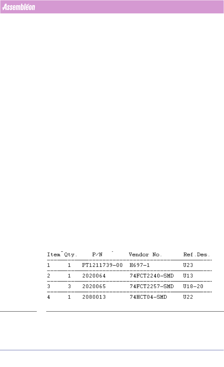
2.10 How to use a BOM file
BOM (Bill Of Materials) files are text-files that contain reference designators,
Vendor names and possibly even more component information
(see FIGURE 1
on page 29). With a BOM-file it is possible to select components from CAD-
data, or update component information in an MDF-file. A BOM-file is useful
when panels, which are quite similar but do not carry exactly the same
components (so-called family-boards) are produced. All panels will be using
the same board-design/cad-data, but each product has its own BOM-file to
specify which components should be mounted and which should not be
mounted.
FIGURE 1 BOM file - Example
User Manual 4022 591 98247
30 PPS-Pro v8.2 05.07
PPS-Pro GUI
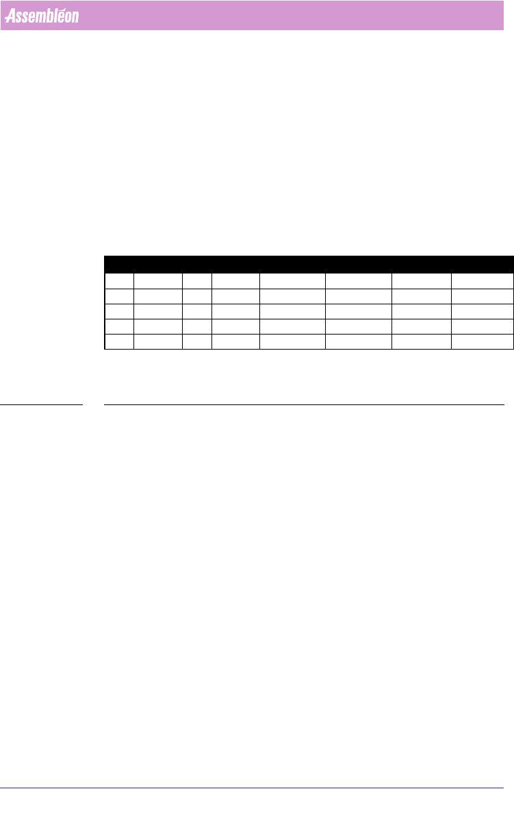
2.11 Difference between “normal” and “strict” BOM
import
■ Normal (see TABLE 2 on page 30):
All components which are present in the CAD-file, are also present in the
MDF-file after importing the BOM-file. Only the component information which
is available in the BOM-file is changed in the created MDF-file.
■ Strict (see TABLE 2 on page 30):
Only components which are present in the BOM-file are present in the MDF-
file after importing the BOM-file. The component information of the BOM-file
is used in the created MDF-file.
C = Component
VN = Vendor number (component info.)
TABLE 2 Principle of normal and strict BOM import
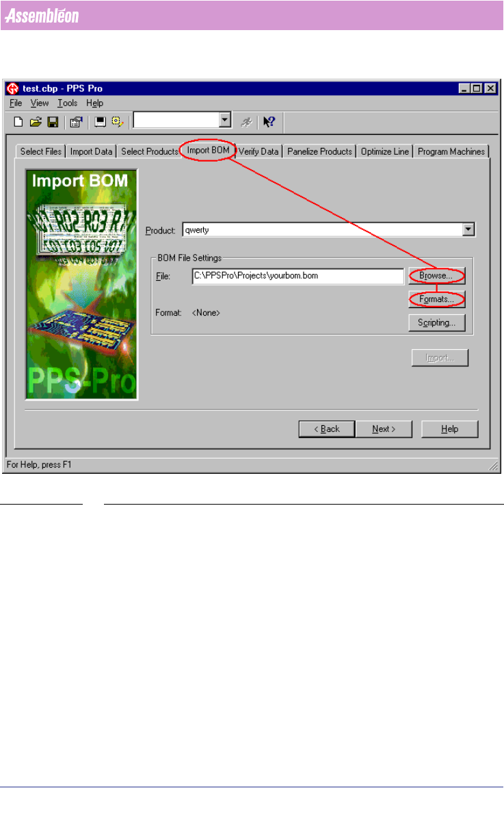
2.11.1 Import via the Import BOM tab
Sometimes a BOM file will be received (long) after a project has been set up,
or a new BOM-file must be imported. When this happens, open the existing
project and use the Import BOM tab to bring in the new BOM.
The procedure for importing a BOM-file via the Import BOM tab is analogue to
the procedure for ‘normal’ importing via the Import Data tab. The only
difference is the startup of the ‘BOM-Formats Explorer’.
To start the ‘BOM-Formats Explorer’, the following steps must be taken (see
SCREEN 22 on page 31):
■ Select the Import BOM tab
■ Press the Browse... button and browse to the BOM-file
■ Press the Formats... button to startup the ‘BOM-Formats Explorer’ and
select the correct format from the list. If no correct format is available, a
new format must be made
(see 2.12.1 on page 32) from point 10.
CAD BOM MDF after normal import MDF after strict import
C1 VN=2 C1 VN=1 C1 VN=1 C1 VN=1
C2 VN=4 C2 VN=2 C2 VN=2 C2 VN=2
C3 VN=6 C4 VN=4 C3 VN=6 C4 VN=4
C4 VN=8 C4 VN=4
C5 VN=9 C5 VN=9
4022 591 98247 User Manual
05.07 PPS-Pro v8.2 31
PPS-Pro GUI
SCREEN 22 Import BOM Existing Project
2.12 BOM Formats
A BOM-format must be available for every BOM-file which will be imported.
This paragraph explains how to create, edit, remove and copy a BOM-format.
All these action can be started from the ‘BOM-Formats Explorer’
(see SCREEN
23 on page 32).