PPS Pro version 8.2 - 第43页
4022 591 98 247 User Manual 05.07 PPS-Pro v8.2 39 PPS-Pro GUI SCREEN 30 BOM Form at Properti e s - Edit 2.12.3 Remo ve a BOM f ormat T o r e m o v e a n e x i s t i n g f o r m a t j u s t s e l e c t a f o r m a t a n d…
User Manual 4022 591 98247
38 PPS-Pro v8.2 05.07
PPS-Pro GUI
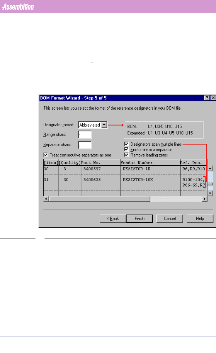
■ Separator chars textfield: Enter the character used in the BOM-file that
separates the reference designators. A comma (,) is the default character.
■ Designators span multiple lines check box: Select this check box if the
reference designators occupy more than one line. If each line ends up with
a separator, the End-of-line is a separator check box must also be selected.
■ Remove leading zeros check box: Check this box, if leading zeros in
reference designators must be ignored. For example, reference designator
C1 would equal C01, U6 would equal U06, and so on. If you choose not to
remove leading zeros, PPS-Pro will consider C1 to be different from C01.
SCREEN 29 BOM Format - Step 5
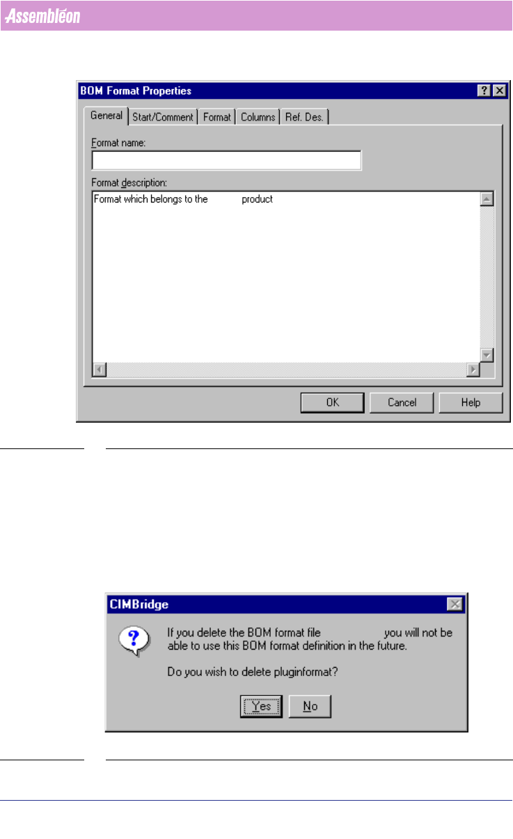
2.12.2 Edit an existing BOM format
To start editing an existing format just press the Edit icon (see SCREEN 23 on
page 32) of the ‘BOM-Formats Explorer’.
After pressing this icon a window appears with five tabs (see SCREEN 30 on
page 39). Each tab is analogous to a BFW step (see 2.12.1 on page 32).
4022 591 98247 User Manual
05.07 PPS-Pro v8.2 39
PPS-Pro GUI
SCREEN 30 BOM Format Properties - Edit
2.12.3 Remove a BOM format
To remove an existing format just select a format and press the Delete icon
(see SCREEN 23 on page 32) of the ‘BOM-Formats Explorer’. A dialog appears
with the question whether the format must be deleted or not (see SCREEN 31
on page 39). Press the Yes button do delete the format or press the No button
to maintain the format.
SCREEN 31 BOM Format - Delete - Confirm
User Manual 4022 591 98247
40 PPS-Pro v8.2 05.07
PPS-Pro GUI
2.12.4 Copy a BOM format
To copy an existing format just select a format and press the Copy icon (see
SCREEN 23 on page 32) of the ‘BOM-Formats Explorer’. The name of the copied
file is ‘Copy of <initial format name>’.
2.13 Graphical/MDF editor
NOTE: Basic help on functionality can be found via the help in the Cimbridge
Graphical Editor (MDF editor). For details on help, go to the
Help menu and
click Help Contents then click a menu item.
NOTE: General information in the Graphical/MDF editor on the opened Product can
be done via Menu:
Info > Info Drawing
2.13.1 Entering board thickness
Board thickness can be set via the Set > Board Thickness command. This will
define the board thickness of the PCB in the MDF file. Setting correct infor
-
mation about the thickness of the PCB is neccessary before a calculation for
an A-Series line can be started.
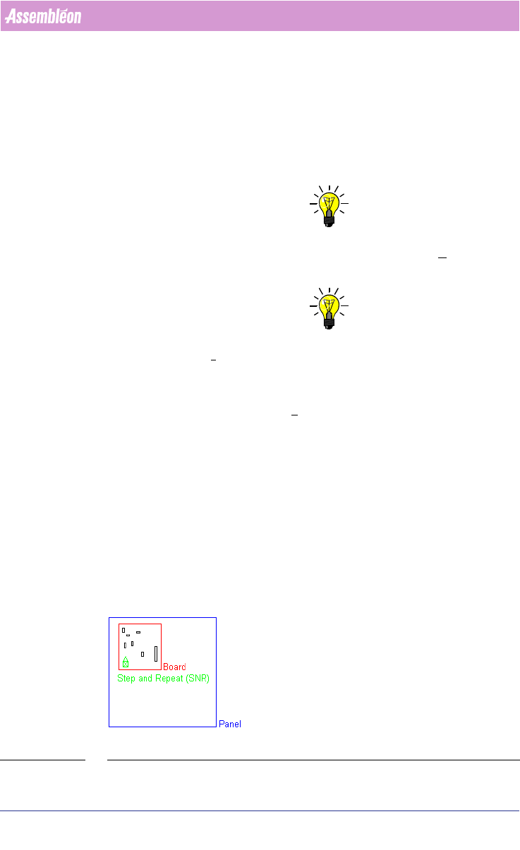
2.13.2 Panel, board, SNR symbol and board id
A PCB is referred to as a panel in an mdf file. A panel may consist of one or
more boards (circuits)
(see FIGURE 2 on page 40).
In an mdf file, each board is represented by its own SNR symbol. The SNR
symbol can be considered a placeholder for the components that belong to the
board the SNR symbol represents.
FIGURE 2 Panel