PPS Pro version 8.2 - 第47页
4022 591 98 247 User Manual 05.07 PPS-Pro v8.2 43 PPS-Pro GUI 2.13.4 Entering fiducials When th e smartca d importer has been used, often fidu cials hav e to be a dded manually via the MDF editor . Th is can be done as f…
User Manual 4022 591 98247
42 PPS-Pro v8.2 05.07
PPS-Pro GUI
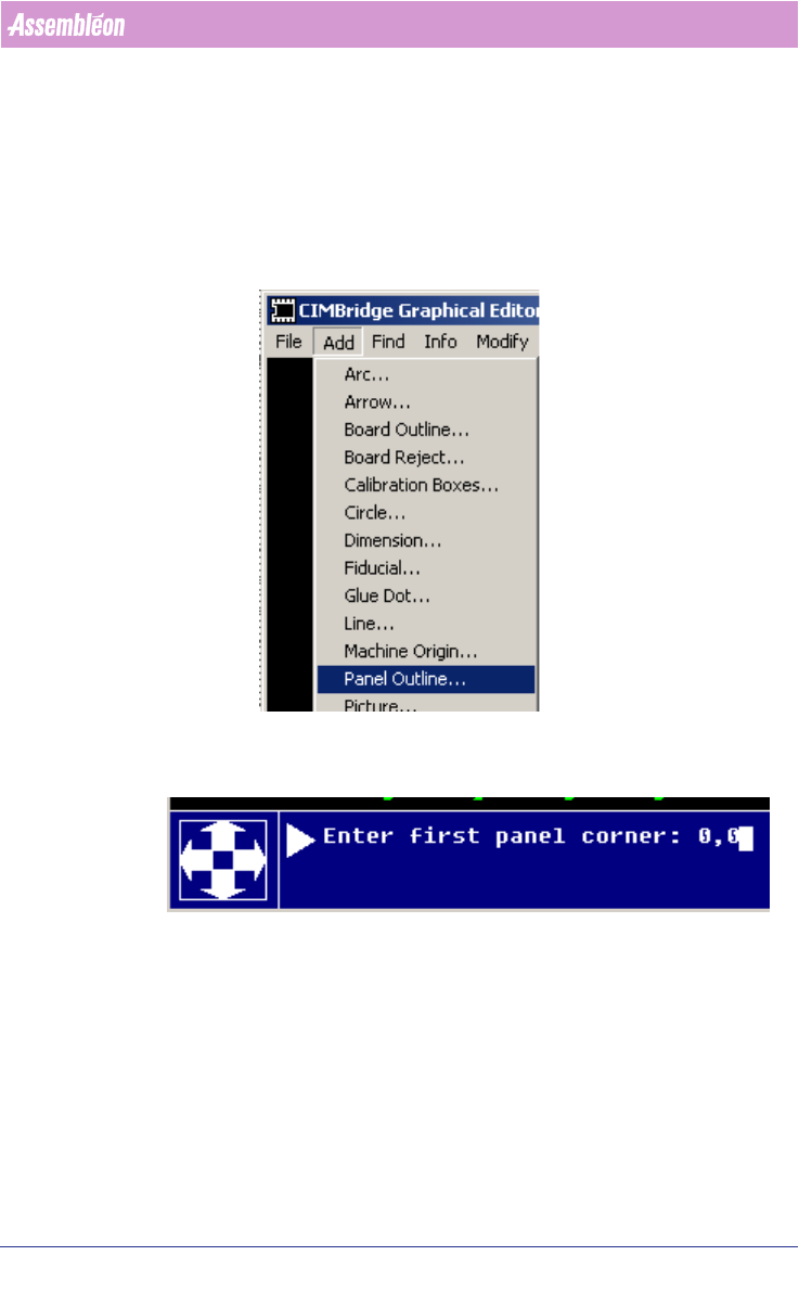
2.13.3 Entering panel outline
When the smartcad importer has been used the panel outline has to be added
manually with the MDF editor, this can be done as follows:
1. Start MDF edit on the imported PCB (Select view button)
2. Select Add > Panel outline
3. Enter the X, Y coordinates of the PCB below, on this screen:
4. After the first corner has been entered, the dialog continues and asks for
the second corner. Enter these coordinates (X,Y) and enter. Now the panel
outline will be shown.
Note that for adding board (=circuit) outlines, first draw the circuit contour
and make this one symbol with Symbol > Build symbol, then use Add >
Board outline to convert this graphic into the requested contour outline.
Revert to MDF help for further details.
4022 591 98247 User Manual
05.07 PPS-Pro v8.2 43
PPS-Pro GUI
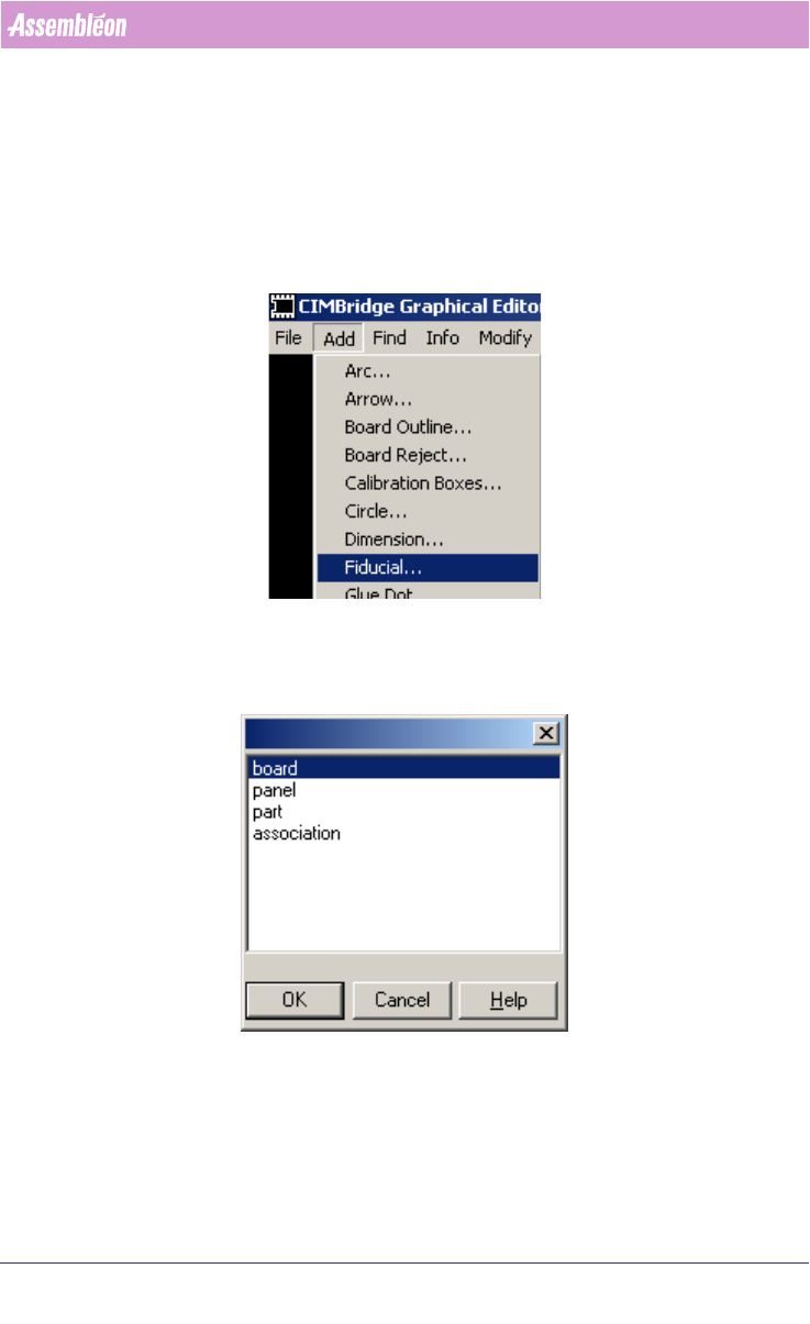
2.13.4 Entering fiducials
When the smartcad importer has been used, often fiducials have to be added
manually via the MDF editor. This can be done as follows:
1. Start MDF edit on the imported PCB.
2. Select Add > Fiducial
Select the type of fiducial that must be entered, note that Panel fidicials are
for the entire PCB whereas board fiducials are for circuits.
Below on the window the fiducial data can be entered:
User Manual 4022 591 98247
44 PPS-Pro v8.2 05.07
PPS-Pro GUI
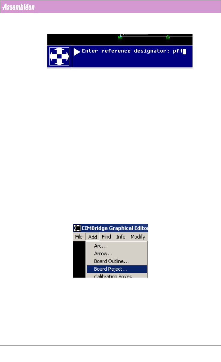
First enter the reference designator, press enter, then enter the (X, Y) coor-
dinates of the fiducial.
After the coordinates have been entered the dialog continues, the user can
select the next fiducial reference designator (the initial designator name is
shown, but the user must change this name), and then again (X, Y) coor
-
dinates of the next fiducials must be entered. After the last fiducial has been
entered delete the prompted reference designator with the backspace key and
press enter to end the data entry action.
Although it is possible to enter the coordinates by clicking on the PCB’s user
interface this is generally only done in cases some object is already present
that is not classified as fiducial yet. (Refer to the help menus of the mdf
editor to obtain more information about the various possibilities that are
present.)
2.13.5 Entering badmarks
After CAD import badmark information is often not present. The following
steps can be followed to add badmarks in the MDF file:
1. Start MDF edit on the imported PCB.
2. Select Add > Board reject
3. Select the requested badmark type: