PPS Pro version 8.2 - 第49页
4022 591 98 247 User Manual 05.07 PPS-Pro v8.2 45 PPS-Pro GUI Boar d Rej ects r elate to circui ts P anel R eject s relate to PCBs or to Ar eas (A-Series) Floating Boar d Rej ects r elate to cir cuits , but can have diff…
User Manual 4022 591 98247
44 PPS-Pro v8.2 05.07
PPS-Pro GUI
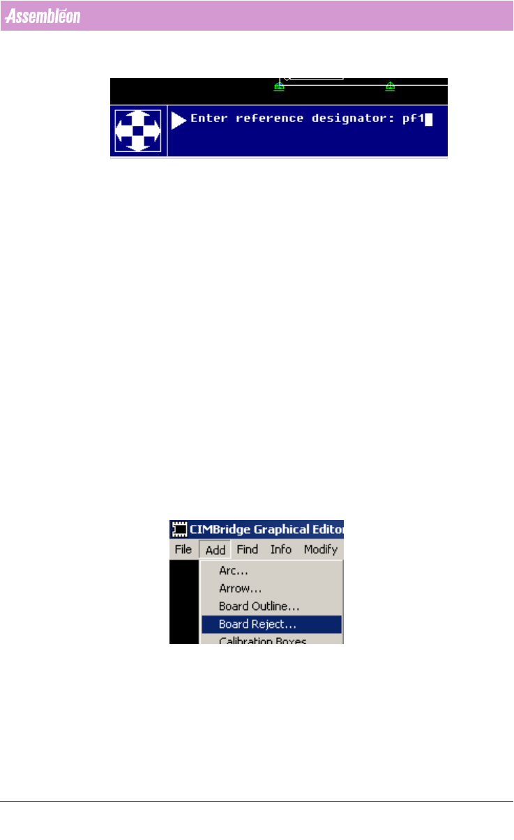
First enter the reference designator, press enter, then enter the (X, Y) coor-
dinates of the fiducial.
After the coordinates have been entered the dialog continues, the user can
select the next fiducial reference designator (the initial designator name is
shown, but the user must change this name), and then again (X, Y) coor
-
dinates of the next fiducials must be entered. After the last fiducial has been
entered delete the prompted reference designator with the backspace key and
press enter to end the data entry action.
Although it is possible to enter the coordinates by clicking on the PCB’s user
interface this is generally only done in cases some object is already present
that is not classified as fiducial yet. (Refer to the help menus of the mdf
editor to obtain more information about the various possibilities that are
present.)
2.13.5 Entering badmarks
After CAD import badmark information is often not present. The following
steps can be followed to add badmarks in the MDF file:
1. Start MDF edit on the imported PCB.
2. Select Add > Board reject
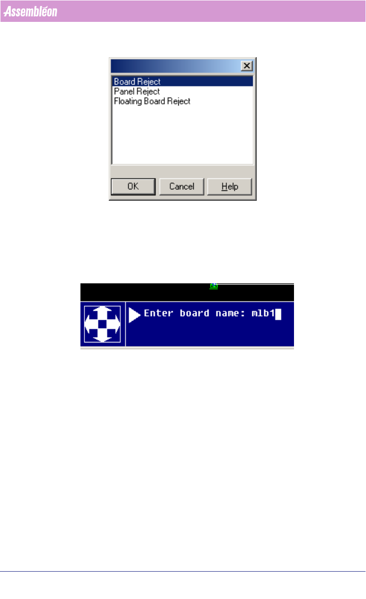
3. Select the requested badmark type:
4022 591 98247 User Manual
05.07 PPS-Pro v8.2 45
PPS-Pro GUI
Board Rejects relate to circuits
Panel Rejects relate to PCBs or to Areas (A-Series)
Floating Board Rejects relate to circuits, but can have different locations than
the circuits themselves.
4. Complete the data entry, example for a board badmark:
5. Enter the location (X, Y) coordinates, or click on the location in the PCB
where the badmark should occur.
6. When the requested badmark(s) is/are present press enter to complete this
data entry.
Note that board rejects relate to a board (=circuit) these are copied along with
the circuits.
2.13.6 Entering reference holes
After CAD import information about reference holes is not always present,
this can be important for FCM and FCM Multiflex machines. The optimizer for
these machines requires one or 2 (Multiflex) reference holes to be defined.
These can be entered as follows:
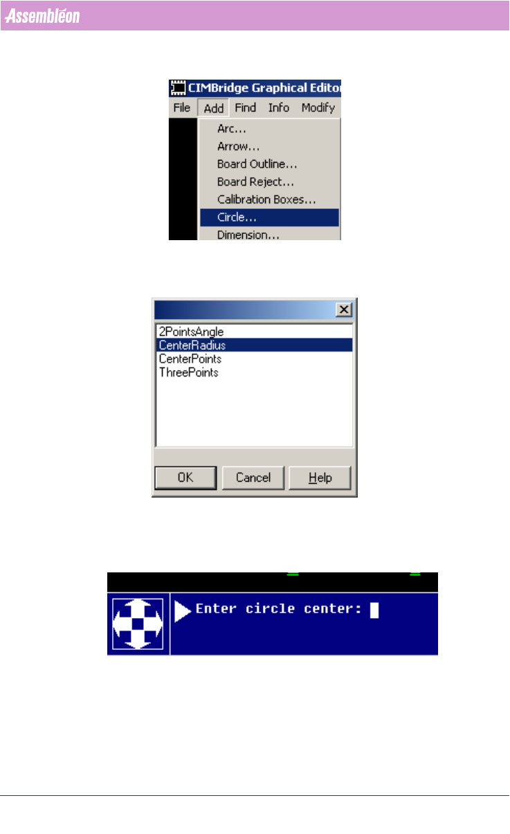
1. Start MDF edit on the imported PCB.
2. Select Add > Circle
User Manual 4022 591 98247
46 PPS-Pro v8.2 05.07
PPS-Pro GUI
3. Select one of the presented types:
CenterRadius is a normal circuit, the remainder of this example uses this type.
4. Enter the (X, Y) coordinates of the circle center:
5. Enter the radius of the circle.
6. Steps 4 and 5 can be repeated until all circles have been entered.
7. Finally press enter (as circle center) to complete the data entry.
To turn a circle into a reference hole proceed as follows: