PPS Pro version 8.2 - 第63页
4022 591 98 247 User Manual 05.07 PPS-Pro v8.2 59 PPS-Pro GUI 2.21.2 Delete Gr oup This function can be applied t o bot h fiducial arr ang e men t and ba dmark groupin g. T o del ete the groupin g eith er fiducial or ba …
User Manual 4022 591 98247
58 PPS-Pro v8.2 05.07
PPS-Pro GUI
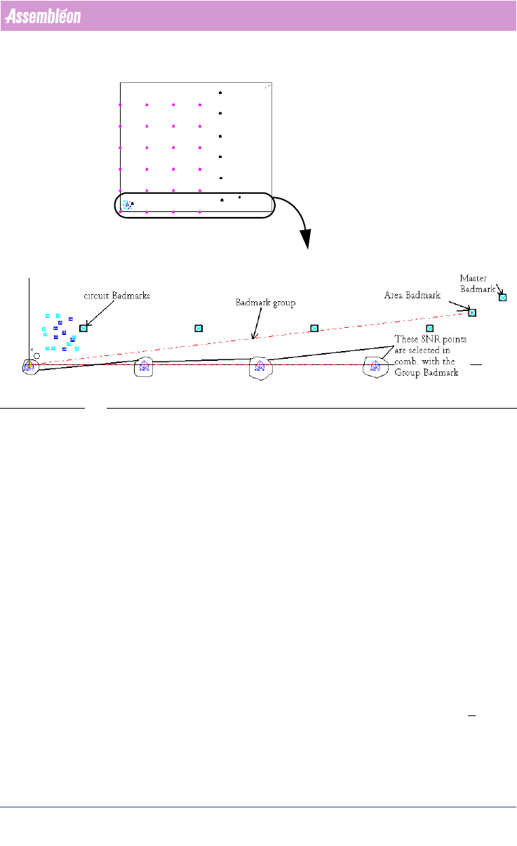
SCREEN 36 Specify an Area badmark
The Area badmarks are manually entered with the MDF editor as panel
badmarks but they must be named as follows:
<name>@<panel_badmark_name>
The Area badmarks can be used to make badmark processing fast, a Badmark
is only read if a higher level badmark is found ‘bad’, on a good PCB only the
highest level badmarks are read, at the moment the system determines that
these are OK it is allowed to place components on the underlying circuits. If
this is not the case then the machine will inspect the lower level badmarks, to
find out on which circuit(s) no parts have to be placed.
2.21 Common grouping functions in the MDF editor
These functions are available when grouping mode is active.
2.21.1 Add to Group
This function can be applied to both fiducial arrangement and badmark
groups. To add a fiducial/ step-and-repeat/ panel badmark etc. items, select
the group (dotted line) and the item to be added to the group. Click
Groups >
Add To Group. Now the selected part is added to the group.
entire PCB
This part is
shown in detail
4022 591 98247 User Manual
05.07 PPS-Pro v8.2 59
PPS-Pro GUI
2.21.2 Delete Group
This function can be applied to both fiducial arrangement and badmark
grouping. To delete the grouping either fiducial or badmark, select the
grouping (the dotted line) and then click
Groups > Delete Group.
2.21.3 Delete From Group
This function can be applied to both fiducial arrangement and badmark
grouping. To delete from the group, select the group (dotted line) and the
part to be deleted from the group. Click
Groups > Delete From Group. Now
the selected part is deleted from the group.
2.21.4 Select Group Items
This function can be applied to both fiducial arrangement and badmark
grouping. Select the group (dotted line) then click
Groups > Select Group
Items, now all the parts are selected which are set to the group.
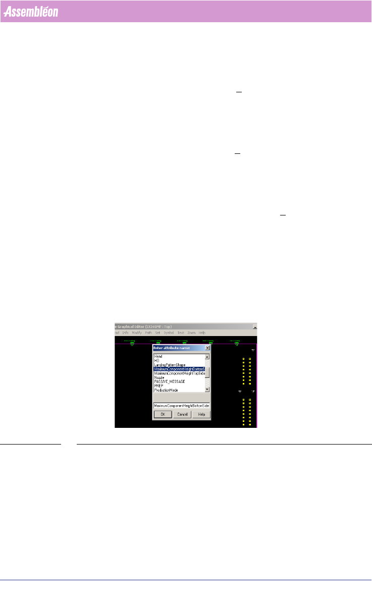
2.22 Initial Panel component Height
In the MDF-Editor it’s possible to add the component height. The optimizer
will change the movement of the transport and head accordingly. This can
make a difference in output time because the traveltime will be
minimized.
(see SCREEN 37 on page 59)
SCREEN 37 Initial panel component height
Select the Panel and go to Modify/Attributes/Add and set manually the
component height. Repeat this for the bottom-side (by selecting the panel on
the bottom-side).
User Manual 4022 591 98247
60 PPS-Pro v8.2 05.07
PPS-Pro GUI
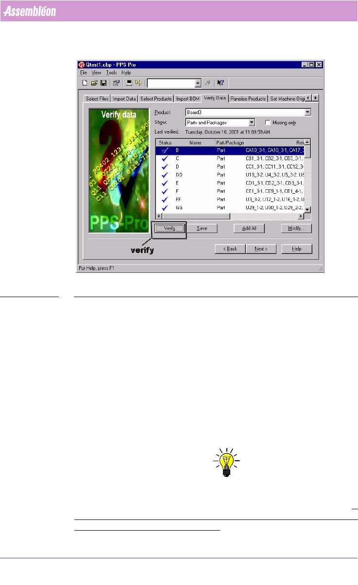
2.23 Verify the component data
SCREEN 38 Verify Data
If a CAD file was imported and not all the parts were present in the PSI file,
you can go to verify data, define them, and add them to the PSI file. If CAD
import resulted in unwanted classification ‘TH’ (=Through Hole) of SMD parts,
then re-import the PCB again, before proceeding with successive calculations.
For undefined packages check if the creation of an alias in PSI is possible
before creating an entirely new package definition. In the verify data function
it is possible to select either action. It is also possible to create alias names for
packages in the PSI file by means of the PSI editor (PIM). Another alternative
is to specify Alias names for existing names in a cad overrides file during cad
import.
2.24 Line Optimize Tab
NOTE: If Multiple Cells (combination of Powerline, GemLine and A-series machines
are used) or Multiple different vendor placement machines are used the tab
Optimize Line must be used to distribute the components over the line.
If
only one cell is in the line configuration (with no other machines in the line)
it is not necessary to do Optimize Line!