PPS Pro version 8.2 - 第64页
User Manual 4022 591 98247 60 PPS-Pro v8.2 05.07 PPS-Pr o GUI 2.23 V erify the component data SCREEN 38 V erify Data If a CAD file w as imported and n ot all th e part s wer e present in th e PSI file , you can g o to ve…
4022 591 98247 User Manual
05.07 PPS-Pro v8.2 59
PPS-Pro GUI
2.21.2 Delete Group
This function can be applied to both fiducial arrangement and badmark
grouping. To delete the grouping either fiducial or badmark, select the
grouping (the dotted line) and then click
Groups > Delete Group.
2.21.3 Delete From Group
This function can be applied to both fiducial arrangement and badmark
grouping. To delete from the group, select the group (dotted line) and the
part to be deleted from the group. Click
Groups > Delete From Group. Now
the selected part is deleted from the group.
2.21.4 Select Group Items
This function can be applied to both fiducial arrangement and badmark
grouping. Select the group (dotted line) then click
Groups > Select Group
Items, now all the parts are selected which are set to the group.
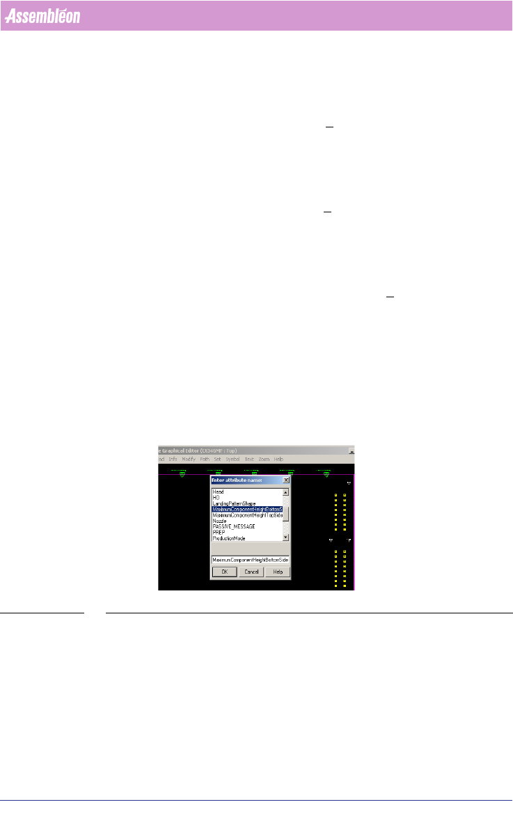
2.22 Initial Panel component Height
In the MDF-Editor it’s possible to add the component height. The optimizer
will change the movement of the transport and head accordingly. This can
make a difference in output time because the traveltime will be
minimized.
(see SCREEN 37 on page 59)
SCREEN 37 Initial panel component height
Select the Panel and go to Modify/Attributes/Add and set manually the
component height. Repeat this for the bottom-side (by selecting the panel on
the bottom-side).
User Manual 4022 591 98247
60 PPS-Pro v8.2 05.07
PPS-Pro GUI
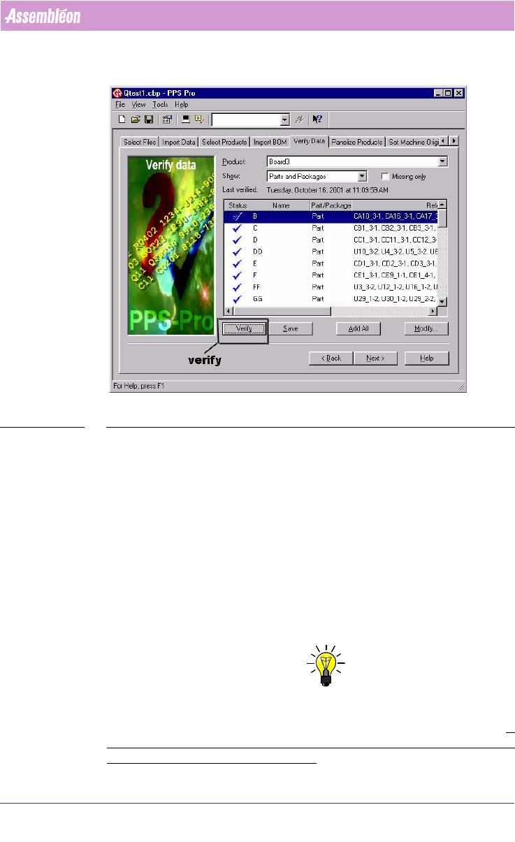
2.23 Verify the component data
SCREEN 38 Verify Data
If a CAD file was imported and not all the parts were present in the PSI file,
you can go to verify data, define them, and add them to the PSI file. If CAD
import resulted in unwanted classification ‘TH’ (=Through Hole) of SMD parts,
then re-import the PCB again, before proceeding with successive calculations.
For undefined packages check if the creation of an alias in PSI is possible
before creating an entirely new package definition. In the verify data function
it is possible to select either action. It is also possible to create alias names for
packages in the PSI file by means of the PSI editor (PIM). Another alternative
is to specify Alias names for existing names in a cad overrides file during cad
import.
2.24 Line Optimize Tab
NOTE: If Multiple Cells (combination of Powerline, GemLine and A-series machines
are used) or Multiple different vendor placement machines are used the tab
Optimize Line must be used to distribute the components over the line.
If
only one cell is in the line configuration (with no other machines in the line)
it is not necessary to do Optimize Line!
4022 591 98247 User Manual
05.07 PPS-Pro v8.2 61
PPS-Pro GUI
Select the PPS-Pro tab Optimize Line. And run the run time balancer. The
components are divided between the different cell(s).
NOTE: Please check the log to find out if certain parts are skipped in all machines.
Check if the number of assigned parts to all machines is equal to the number
of parts on the PCB.
Refer to the run time balancer recipe document Manual RTB recipe 12NC 4022
591 98825.
NOTE: It may happen that the Line optimizer does not assign any parts to a
machine. This can be caused by restrictions such as: Feeder/tray does not fit
on the machine, No tooling to handle the part.
2.25 Program Machines Tab
2.25.1 Specify project related optimizer settings
To specify the optimizer settings in PPS-Pro the following things must be
done:
1. Go to the Program Machines tab and press the Settings... button.
2. Press the Modify button in the General controls frame of the appearing
window.
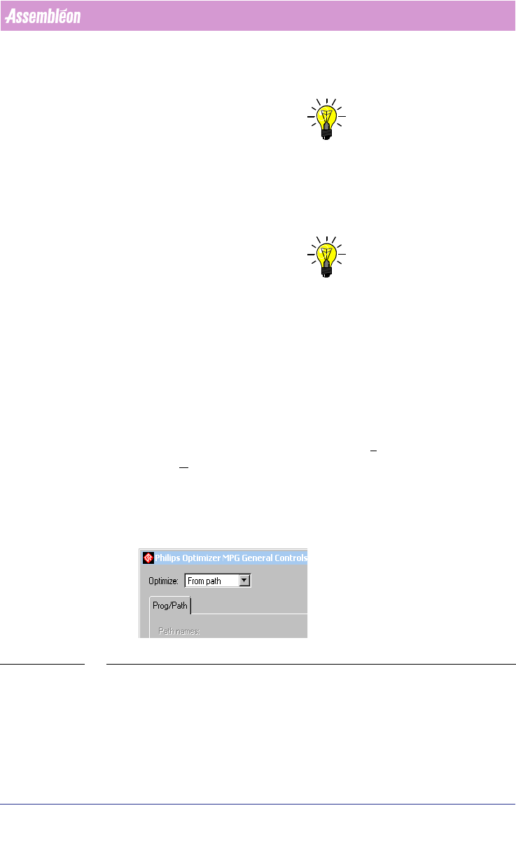
The Optimize: can be set to “From path” and “From MDF” (see SCREEN 39 "Set
From Path or From MDF" on page 61).
SCREEN 39 Set From Path or From MDF
a) From Path: This option is set if a Optimizer Line is used for
distribution.
(see 2.24 "Line Optimize Tab" on page 60).