PPS Pro version 8.2 - 第86页
User Manual 4022 591 98247 82 PPS-Pro v8.2 05.07 PPS-Pr o GUI 2.37 Step 6: P erform a calculation using the constraint file ■ Save the con strain ts as an .l cf file Befor e a calculation can be done with the specified c…
4022 591 98247 User Manual
05.07 PPS-Pro v8.2 81
PPS-Pro GUI
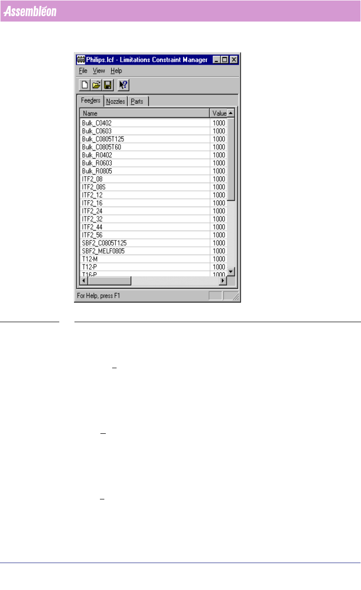
SCREEN 57 LCM Set
2.34 Step 3: Set available feeders
In the Feeders tab the available amount of feeders can be set per feedertype.
Select the right row (feeder) and double-click the ‘value’ field. Now the Edit
value dialog appears and the appropriate value can be specified.
2.35 Step 4: Set available nozzles
In the Nozzles tab the available amount of nozzles can be set per nozzletype.
Select the right row (nozzle) and double-click the ‘value’ field. Now the Edit
value dialog appears and the appropriate value can be specified.
2.36 Step 5: Set available parts
In the Parts tab the available amount of reels /trays /sticks containing a part
type can be set per part type. Select the right row (part) and double-click the
‘Value’ field. Now the Edit value dialog appears and the appropriate value can
be specified.
User Manual 4022 591 98247
82 PPS-Pro v8.2 05.07
PPS-Pro GUI
2.37 Step 6: Perform a calculation using the constraint
file
■ Save the constraints as an .lcf file
Before a calculation can be done with the specified constraints, it has to be
saved as an lcf file (Limitations Constraint File). After that, the lcf file can be
used in the project.
■ Select the lcf file in the project.
To specify the lcf-file, go to the Program Machines tab, select one of the
machines in the applicable cell (this means that these limitations are set per
cell in the line and not for the entire line) and press the
Settings button. In
the General controls frame click the
Modify button. The Assembléon
Optimizer MPG General Controls window appears. In the Machine specific
frame click the
Settings button. Specify the lcf file in the Limitations
Constraint File textbox. Use the Browse... button to browse to the lcf file. Now
the lcf file with all its constraints will be taken into account during the opti
-
mization.
2.38 Reports and Listings
After a successful calculation, several useful reports and listings are
generated. In the next paragraphs an overview of some reports and listings is
given.
2.39 Nozzle setup information (.nzl)
This contains all information on the nozzle setup of the machine it belongs
to. For combined product calculations the information in the .stp files covers
the setup information for all calculated products.
Below is an example of a .nzl file for an ACM with TEU.
Nozzle Setup Report
Machine: "ACM_with_TEU"
Head Number Head Type Nozzle
TEU Number Nozzle
2 O2I2
2 O2I4
2 O2I4
2 O2I4
4022 591 98247 User Manual
05.07 PPS-Pro v8.2 83
PPS-Pro GUI
Nozzle Number used
O2I2 1
O2I4 3
An example of a .nzl file for an FCM with 16 Laser Placement Modules is given
below:
Nozzle Setup Report
Machine: "FCM-II-16LAS"
PM Number PM Type Nozzle
1 LASER 4720
2 LASER 4720
3 LASER 4720
4 LASER 4720
5 LASER 4720
6 LASER 4720
7 LASER 4720
8 LASER 4720
9 LASER 4720
10 LASER No_Nozzle
11 LASER No_Nozzle
12 LASER 4730
13 LASER 4730
14 LASER 4730
15 LASER 4730
16 LASER 4730
Nozzle Number used
4720 9
No_Nozzle 2
4730 5
An example of an .nzl file for an AX Base 5 with 20 (Compact) Placement
Robots is given below:
Nozzle Setup Report
Machine: "M-AX5_20"