Covers.pdf - 第11页
COVERS MACHINE COVERS Chapter Issue 2 Sep 09 Technical Reference Manu al 3.11 3. T ilt the top of the panel away from the machine and lif t the panel clear of the location pins at the bottom. Rear Panel T o remove the re…
COVERS
MACHINE COVERS
3.10 Technical Reference Manual Chapter Issue 2 Sep 09
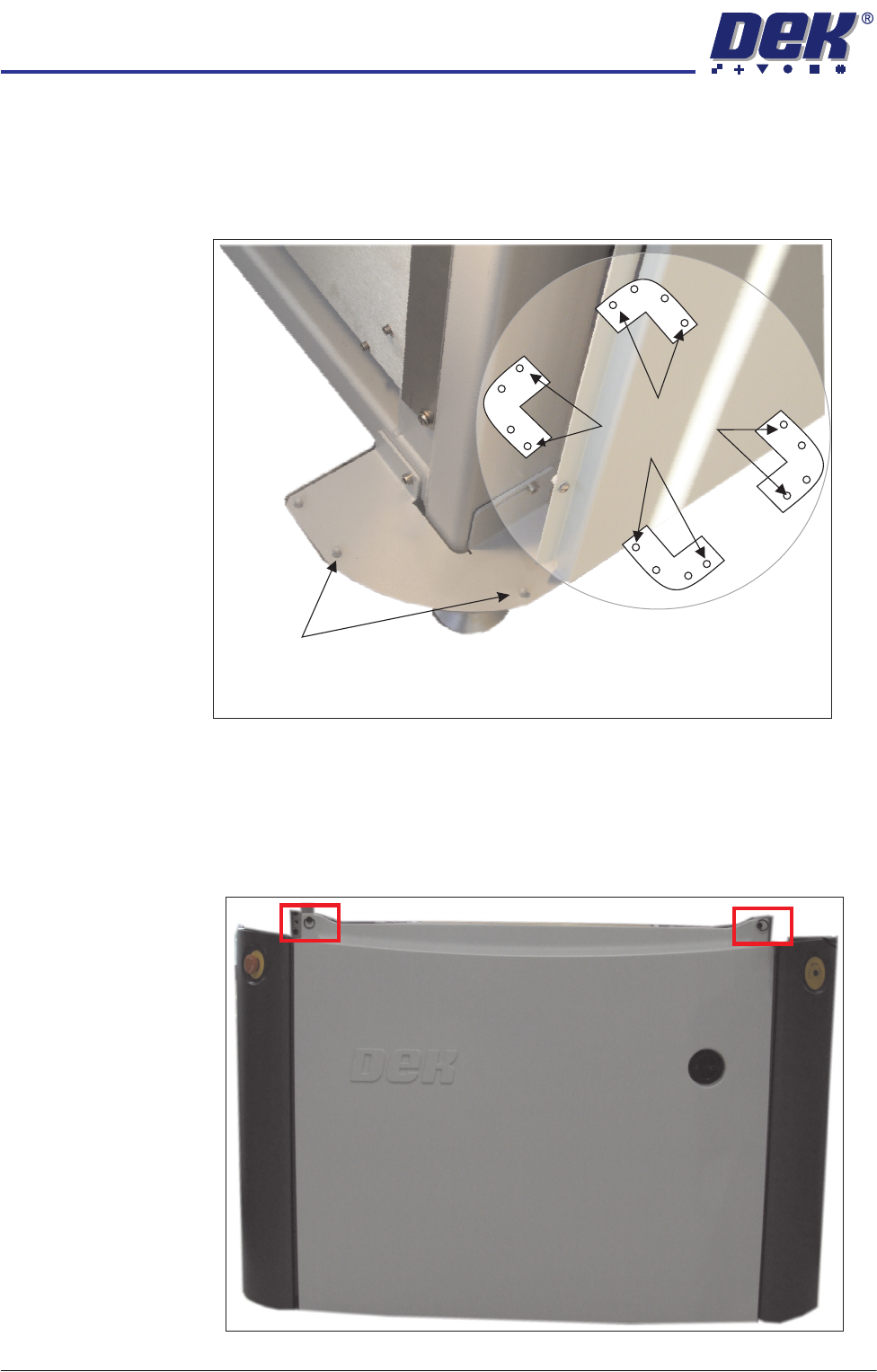
Locating Pins Side, corner, front and rear panels are secured on location pins at the base of
the machine. Plates mounted on each corner of the machine (see vignette
below) house the four pins; the two centre pins are for the corner panels and
two outer pins are for the side, front and rear panels.
Figure 3-7 Mounting Plates
Front Panel To remove the front panel, carry out the following:
1. Open the sliding glass cover.
2. Release the two quarter-turn ring fasteners located externally at the top
corners of the panel.
Corner Panel
Location Pins
View on Base of Machine
Location Pins
Side, Front &
Rear Panels
COVERS
MACHINE COVERS
Chapter Issue 2 Sep 09 Technical Reference Manual 3.11
3. Tilt the top of the panel away from the machine and lift the panel clear of the
location pins at the bottom.
Rear Panel To remove the rear panel, carry out the following:
1. Lift the rear printhead cover.
2. Release the two quarter-turn ring fasteners located externally at the top
corners of the panel.
3. Tilt the top of the panel away from the machine and lift the panel clear of the
location pins at the bottom.
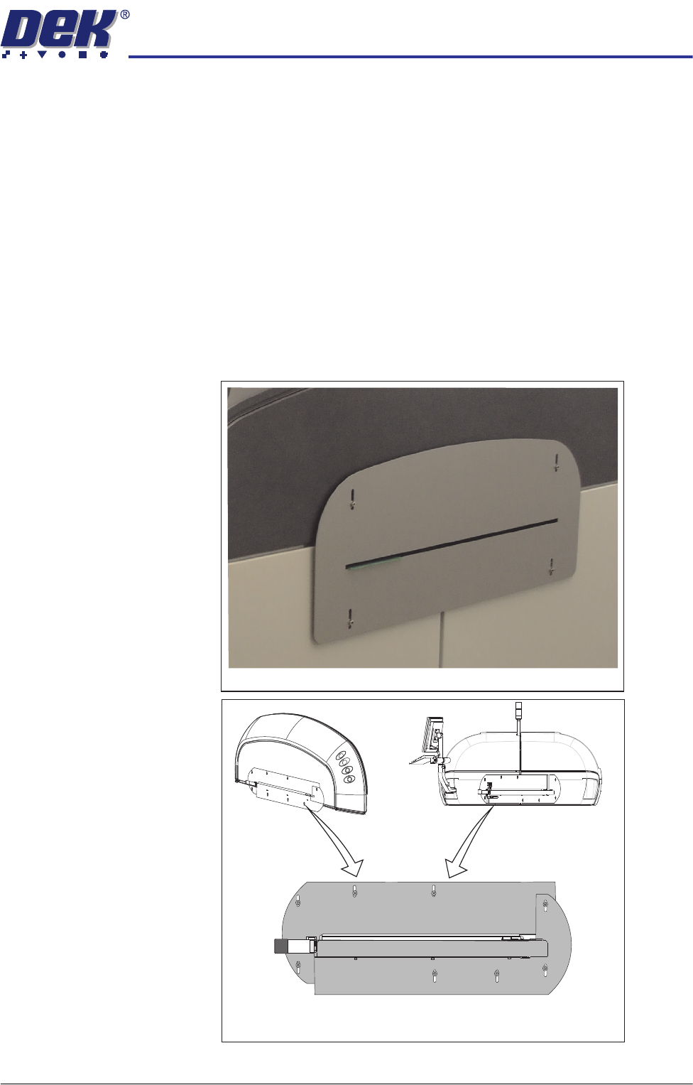
Safety Covers Safety covers are fitted to the side panels to protect personnel from inadvertent
access to the product entry/exit ports.
To remove the safety covers, remove the four securing screws, stand-offs and
washers; remove the cover.
Standard Safety Covers
HTC Safety Covers
(showing the two halves)
COVERS
MACHINE COVERS
3.12 Technical Reference Manual Chapter Issue 2 Sep 09
Upper Side Panels To remove an upper side panel, carry out the following:
1. Lift the sliding glass cover.
2. Lift the rear printhead cover.
3. Remove the safety cover.
4. At the front of the upper side panel, remove the appropriate upper panel
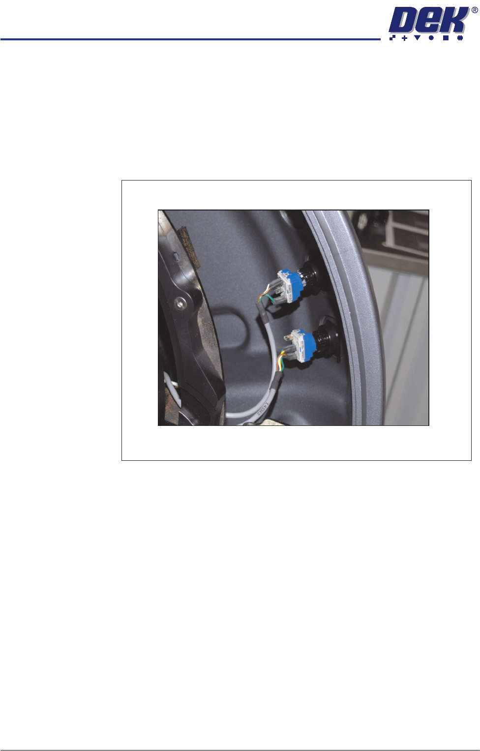
switch contact blocks (System, Jog or Internal light.) The blocks are located
at the rear of the switch bezel.
5. The contact block can be separated from the bezel, (hold the body part to
remove the contact blocks, not the switch wires) by pulling it out of the bezel.
Switches (System, Jog)