Covers.pdf - 第19页
COVERS MACHINE COVERS Chapter Issue 2 Sep 09 Technical Reference Manu al 3.19 7. Remove the earth strap from the botto m of the panel. 8. Remove the p anel. Sliding Glass Cover The sliding glass cover is heav y and requi…
COVERS
MACHINE COVERS
3.18 Technical Reference Manual Chapter Issue 2 Sep 09
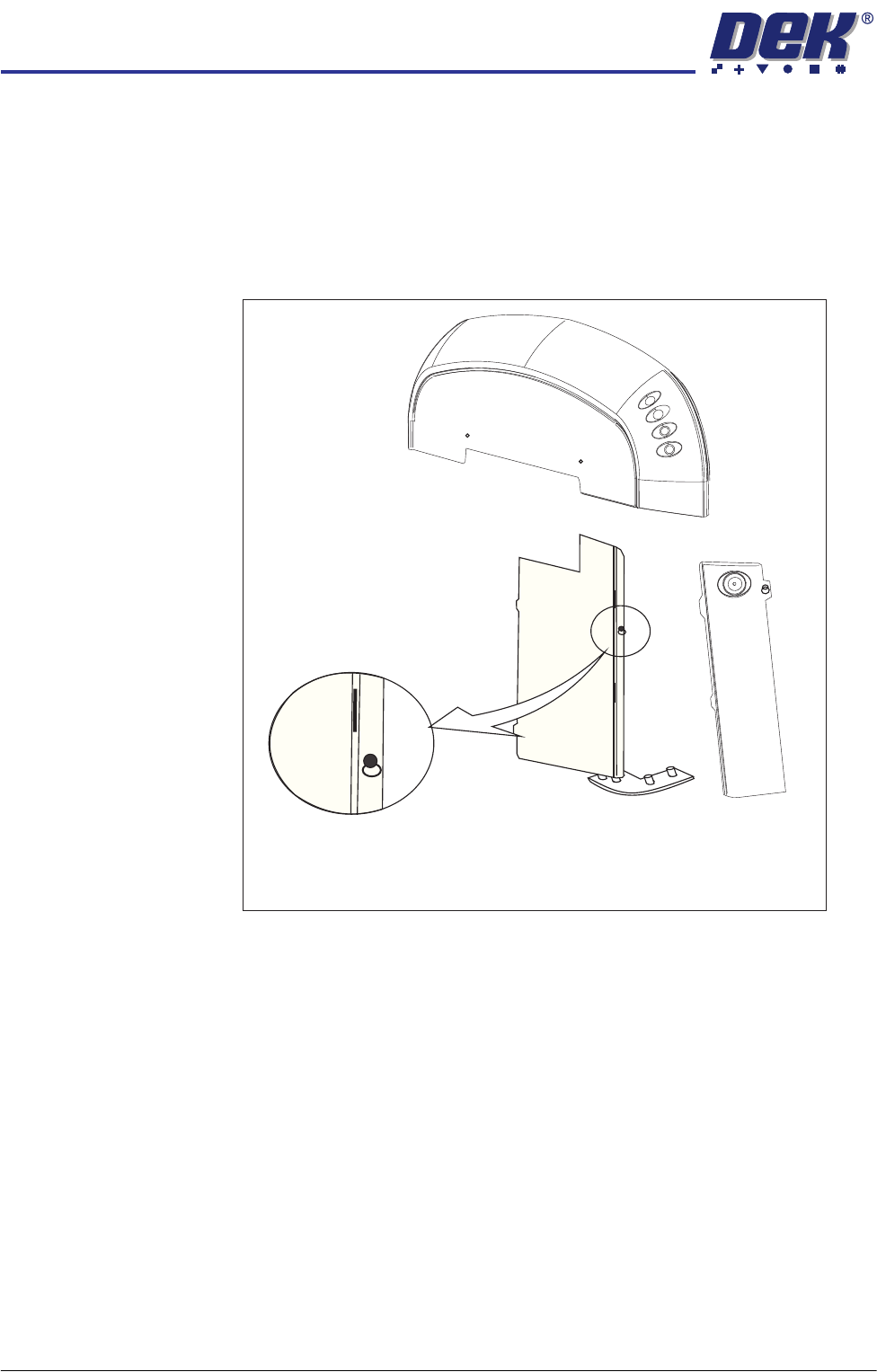
Front Side Cover To remove the front side cover, carry out the following:
1. Open the front printhead cover.
2. Remove the safety cover.
3. Remove the front panel.
4. Locate and release the corner panel quarter- turn ring fastener; lift the corner
panel away to gain access to the front side cover quarter- turn ring fastener.
5. Release the fastener.
6. Lift the front side panel away from the location pin and slide the panel away
from the rear side cover locating tabs. Remove the earth strap from the
bottom of the panel.
7. Remove the panel.
Rear Side Cover To remove the rear side cover, carry out the following:
1. Remove the rear panel.
2. Remove the safety cover.
3. Open the rear printhead cover.
4. Locate and release the corner panel quarter- turn ring fastener; lift the corner
panel away to gain access to the rear side cover quarter- turn ring fastener.
5. Release the fastener.
6. lift the rear side panel away from the location pin and slide the panel away
from the front side cover locating tabs.
Front Side Cover
Quarter-turn Fastener
COVERS
MACHINE COVERS
Chapter Issue 2 Sep 09 Technical Reference Manual 3.19
7. Remove the earth strap from the bottom of the panel.
8. Remove the panel.
Sliding Glass Cover The sliding glass cover is heavy and requires a minimum of two people to lift it
away from its mountings. If the cover needs to be removed; contact DEK
Customer Support Group for further information and the special tools required.
Rear Printhead
Cover
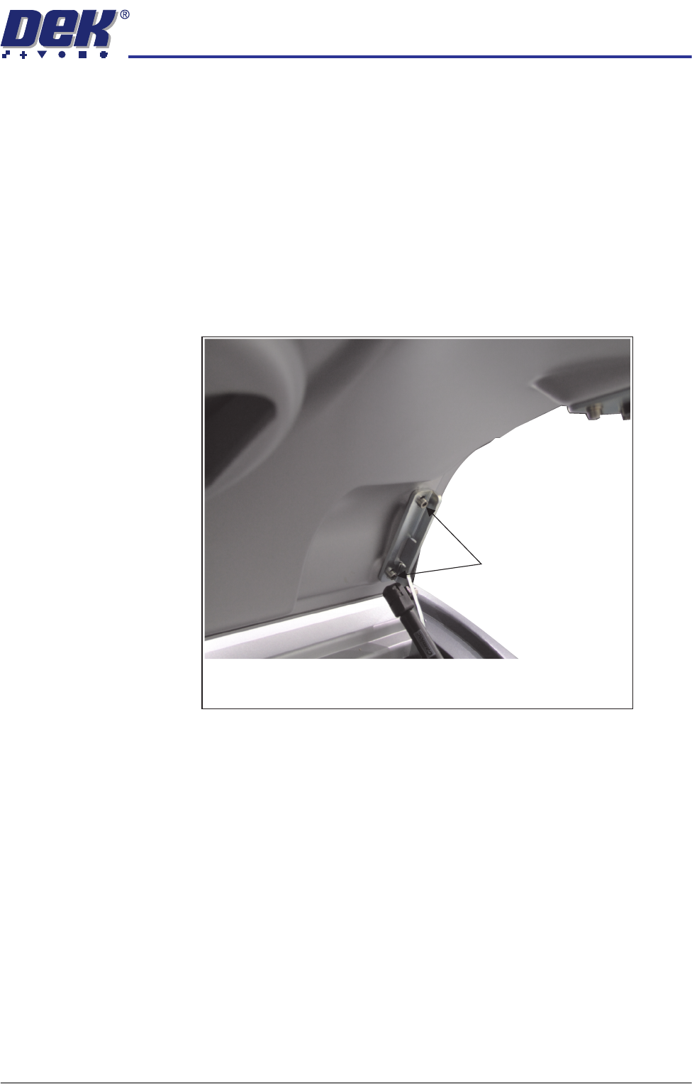
To remove the rear printhead cover:
1. Lift the rear printhead cover.
2. Locate the cover open mechanism.
3. Remove the bracket securing screws from both sides of the lid.
4. Lift the cover away from the machine.
Refitting the Covers NOTE
Before fastening latches ensure that all panels are located on the pins and the
location tabs are fully engaged.
Bracket Securing Screws
View on Right Hand Side of the Cover Assembly
(Cover in the Open Position)
COVERS
MACHINE COVERS
3.20 Technical Reference Manual Chapter Issue 2 Sep 09
Metal Cover
Machine
In order to protect personnel and prevent damage to the machine, eight panels
are fitted to the machine.
The upper part of the machine is protected by the front printhead cover, the rear
fixed printhead cover, the top panel and two upper side panels.
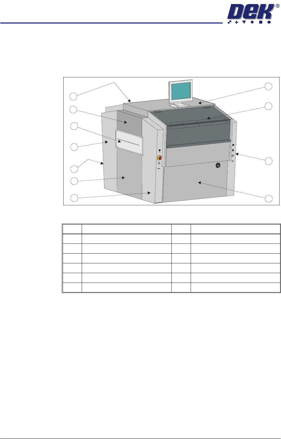
Figure 3-8 Metal Cover Machine
NOTE
Some of the covers can only be removed in a specific order due to the covers
interlocking with each other.
Item Description Item Description
1 Top Panel 7 Rear Panel (opposite front panel)
2 Front Printhead Cover 8 Rear Corner Panel (in 2 positions)
3 Front Right Hand Corner Panel 9 Safety Cover (in 2 positions)
4 Front Panel 10 Upper Side Panel (in 2 positions)
5 Front Left Hand Corner Panel 11 Rear Fixed Printhead Cover
6 Lower Side Panel (in 2 positions)
1
2
3
4
5
6
7
8
9
10
11