Covers.pdf - 第23页
COVERS MACHINE COVERS Chapter Issue 2 Sep 09 Technical Reference Manu al 3.23 Rear Fixed Printhead Cover T o remove the rear fixed printhead cover , carry out the following: 1. Remove the rear p anel (as detailed previou…
COVERS
MACHINE COVERS
3.22 Technical Reference Manual Chapter Issue 2 Sep 09
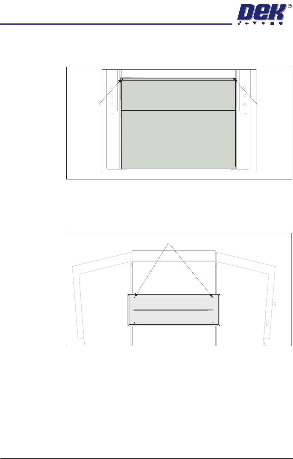
Rear Panel To remove the rear panel, carry out the following:
1. Using a maintenance key, release the two button head quarter-turn fasten-
ers located at the top corners of the panel.
2. Tilt the top of the panel away from the machine and lift the panel clear.
Safety Covers Safety covers are fitted to the side panels to protect personnel from inadvertent
access to the board entry/exit ports.
To remove the safety cover, remove the four safety cover securing screws.
Button Head
Quarter-Turn
Fastener
View on Rear of Machine
Button Head
Quarter-Turn
Fastener
Safety Cover Securing Screws (in 4 positions)
COVERS
MACHINE COVERS
Chapter Issue 2 Sep 09 Technical Reference Manual 3.23
Rear Fixed
Printhead Cover
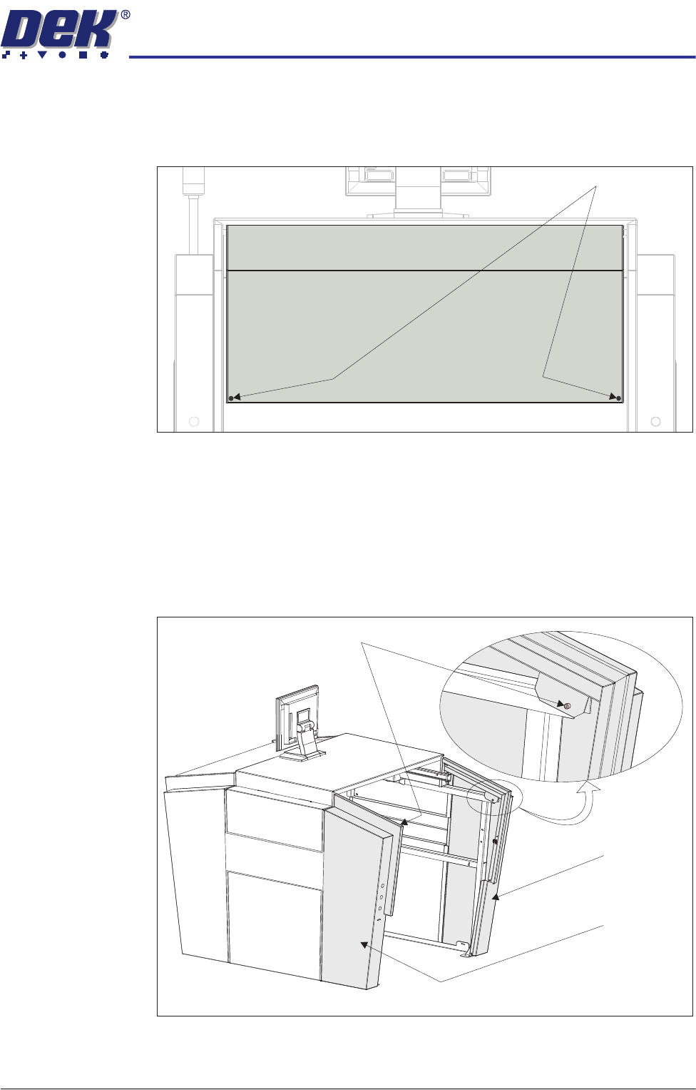
To remove the rear fixed printhead cover, carry out the following:
1. Remove the rear panel (as detailed previously).
2. Remove the two M5 cap head screws.
3. Lift the cover clear of the machine.
Rear Corner Panels To remove the rear corner panels, carry out the following:
1. Remove the corresponding safety cover (as detailed previously).
2. Remove the rear panel (as detailed previously).
3. Remove the rear fixed printhead cover (as detailed previously).
4. Remove the appropriate M5 cap head screw.
5. Lift the panel clear of the machine.
6. Repeat Steps 1, 4 and 5 for the other rear corner panel, if required.
View on Rear of Machine
M5 Cap Head Screws
View on Rear - Right Quarter
M5 Cap Head
Screws
Left Rear
Corner Panel
Right Rear
Corner Panel
COVERS
MACHINE COVERS
3.24 Technical Reference Manual Chapter Issue 2 Sep 09
Front Corner Panels To remove the front corner panels, carry out the following:
1. Open the front printhead cover.
2. Remove the front panel (as detailed previously).
3. Remove the corresponding safety cover (as detailed previously).
NOTE
Before a front corner panel can be removed, the control switches (jog switch
and system switch or jog switch and E Stop) must be disconnected.
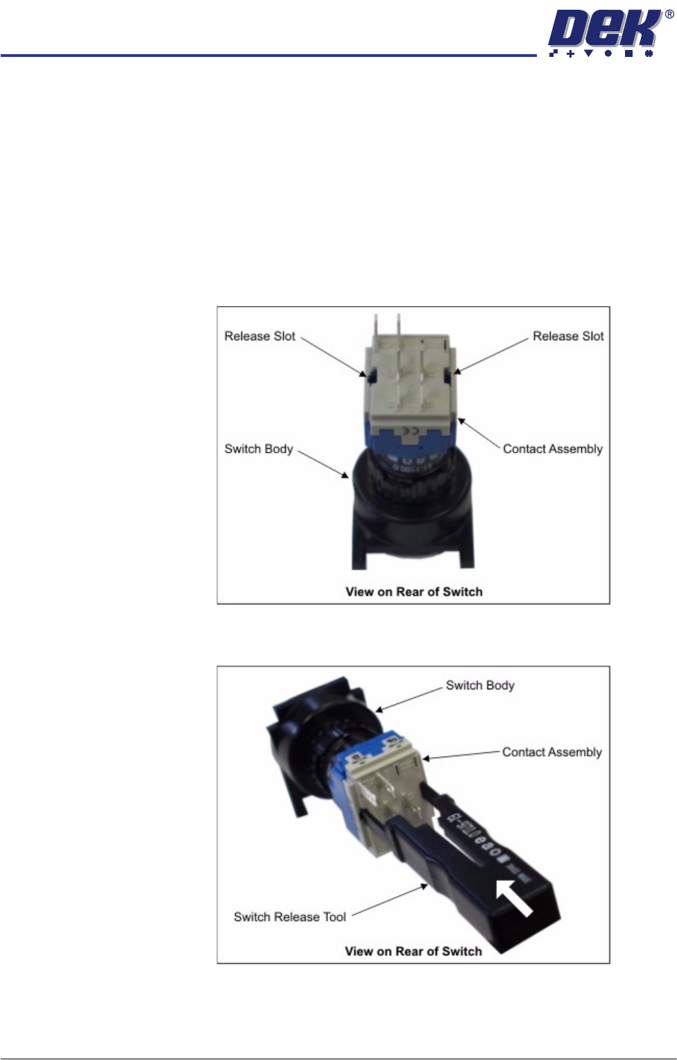
4. To disconnect the system switch and jog buttons carry out the following:
a. Locate the two release slots in the contact assembly part of the switch.
b. Insert the switch release tool (Part No. 188647) into the slots and push
until the release tool clicks into place.
c. Leaving the switch release tool in position, pull the contact assembly from
the switch body.
d. Remove the switch release tool from the contact assembly.