Covers.pdf - 第3页
COVERS MACHINE COVERS Chapter Issue 2 Sep 09 Technical Reference Manu al 3.3 (Button Head Quarter-T urn Fastener figure refers). Af ter releasing the fasten- ers, push downwards on the panel to clear the rear p rinthead …
COVERS
MACHINE COVERS
3.2 Technical Reference Manual Chapter Issue 2 Sep 09
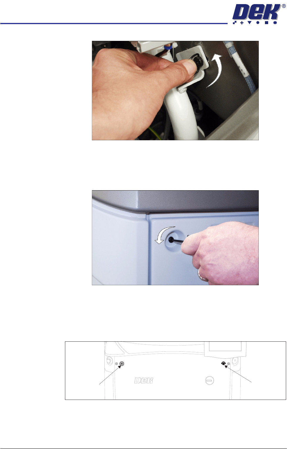
Figure 3-2 Ring Head Quarter-Turn Fastener
Button Head
Quarter-Turn
Fasteners
To remove a panel secured with button head quarter-turn fasteners, using a
4mm Allen key (maintenance key), turn the fastener anti-clockwise by a quar-
ter-turn and pull out.
Figure 3-3 Button Head Quarter-Turn Fastener
Front Panel The front panel is secured by a ring head quarter-turn fastener and a button
head quarter-turn fastener.
1. To remove the front panel of the machine, open the front printhead cover
and locate the two quarter-turn fasteners on the inside of the panel.
2. After releasing the fasteners, tilt the top of the panel away from the machine
and lift clear of the guide pins that locate the panel to the machine frame.
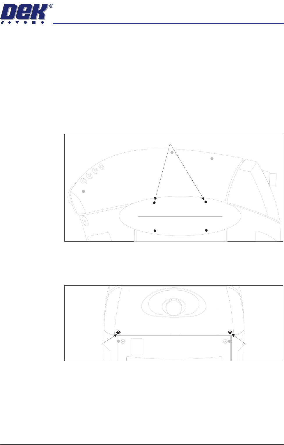
Rear Panel Removal of the rear panel requires a maintenance key to release the two button
head quarter-turn fasteners located externally at the top corners of the panel
Front Panel
Button Head
Quarter-Turn
Fastener
Front Panel
Ring Head
Quarter-Turn
Fastener
COVERS
MACHINE COVERS
Chapter Issue 2 Sep 09 Technical Reference Manual 3.3
(Button Head Quarter-Turn Fastener figure refers). After releasing the fasten-
ers, push downwards on the panel to clear the rear printhead cover, tilt the top
of the panel away from the machine and lift clear of the guide pins that locate
the panel to the machine frame.
Safety Covers Safety covers are fitted to the side panels to protect personnel from inadvertent
access to the board entry/exit ports.
NOTE
For machines fitted with HTC safety covers, refer to the High Throughput
Conveyor Option section later in the chapter.
To remove the safety cover, remove the four safety cover securing screws.
Rear Printhead
Fixed Cover
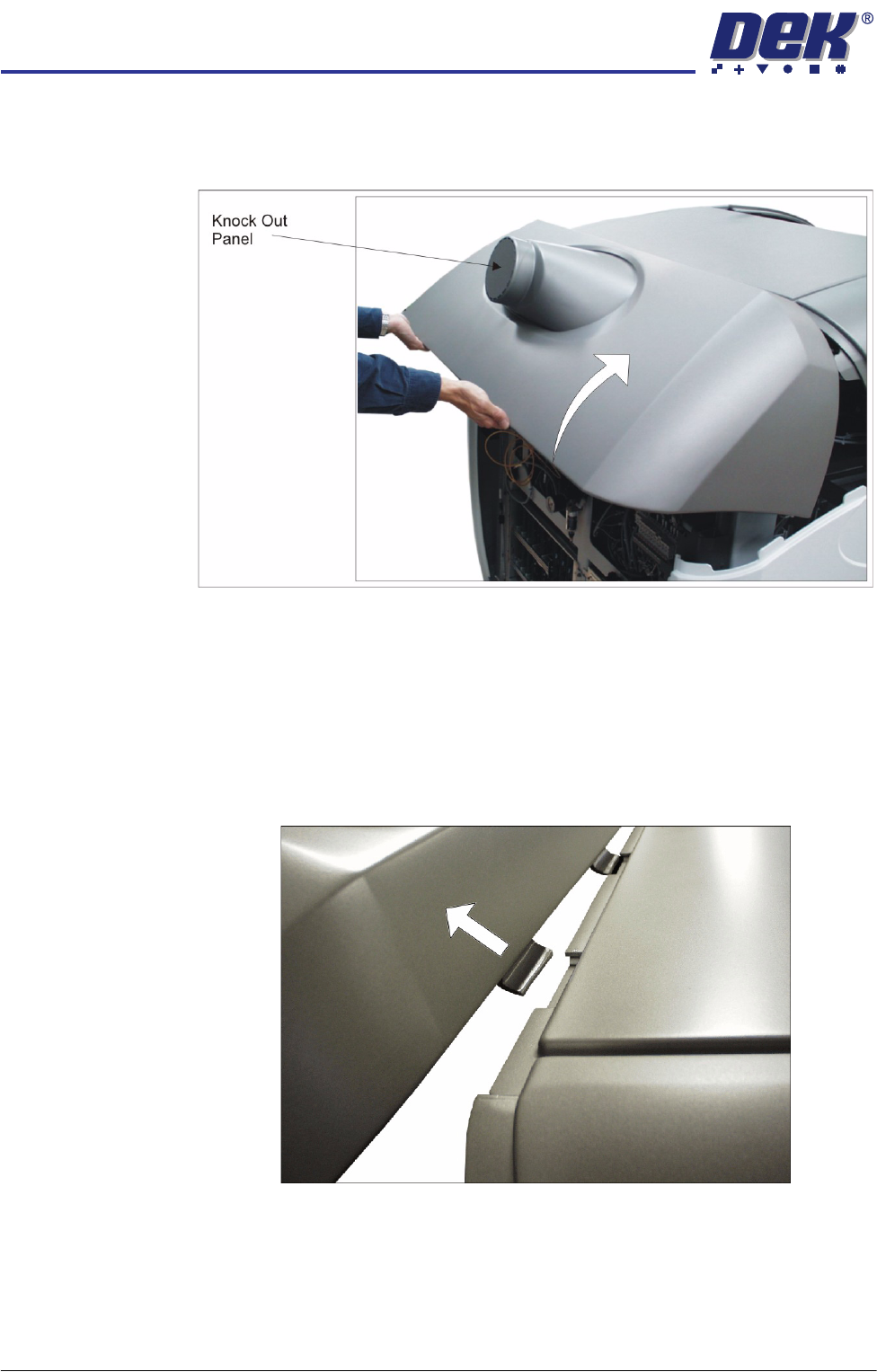
To remove the rear printhead fixed cover, carry out the following:
1. Remove the rear panel.
2. Release the two quarter-turn fasteners that secure the rear printhead cover
to the cover frame.
Safety Cover Securing Screws (in 4 positions)
Rear Printhead
Quarter-Turn
Fastener
Rear Printhead
Quarter-Turn
Fastener
COVERS
MACHINE COVERS
3.4 Technical Reference Manual Chapter Issue 2 Sep 09
3. The rear printhead cover is interlocked with the upper printhead cover using
locating tabs. The rear printhead cover must be lifted to allow the locating
tabs to part.
NOTE
The knock out panel is removed when the printer is connected to a Temper-
ature Control Module (TCM). If a TCM is not fitted the knock out panel must
be intact, or this would contravene the safety requirements the printer is
tested to. Where the knock out panel has been removed and a TCM is not
fitted, DEK recommends fitting a new rear panel.
4. Once the locating tabs have cleared, pull the cover horizontally away from
the machine.