Covers.pdf - 第9页
COVERS MACHINE COVERS Chapter Issue 2 Sep 09 Technical Reference Manu al 3.9 Cover Removal Before removing covers ensure that the supplie s (air and electrical) have been isolate d from the mach ine. Quarter-T urn Ring F…
COVERS
MACHINE COVERS
3.8 Technical Reference Manual Chapter Issue 2 Sep 09
Sliding Glass
Cover Machine
Type iX
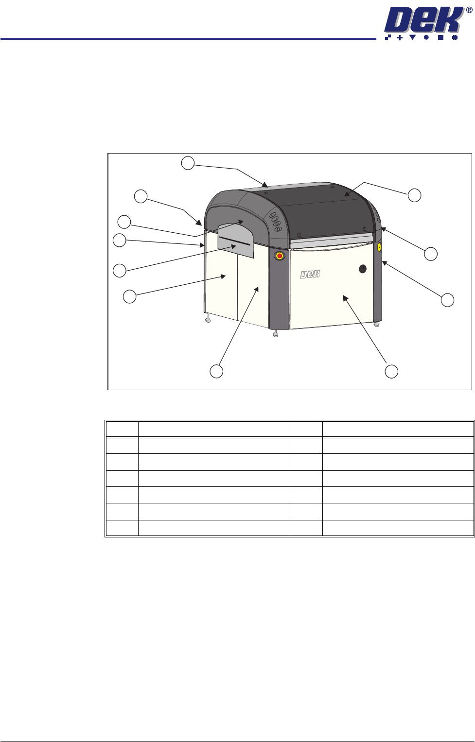
In order to protect personnel and prevent damage to the machine, ten covers
are fitted to the machine.
The sliding glass cover, the rear printhead cover and two upper side panels
which house the control switches protect the upper part of the machine. The
four corner panels, front and rear panels, safety covers and the front and rear
side panels protect the lower part of the machine.
Figure 3-4 Sliding Glass Cover Type iX
NOTE
Some of the covers can only be removed in a specific order due to the covers
interlocking with each other.
Item Description Item Description
1 Sliding Glass Cover 7 Safety Cover (2 positions)
2 Right Hand Upper Side Panel 8 Rear Corner Panel (2 positions)
3 Front Corner Panel (2 positions) 9 Left Hand Upper Side Panel
4 Front Panel 10 Rear Panel
5 Front Side Panel (2 positions) 11 Rear Printhead Cover
6 Rear Side Panel (2 positions)
1
2
3
4
5
6
9
11
10
8
Front Left Quarter View
7
COVERS
MACHINE COVERS
Chapter Issue 2 Sep 09 Technical Reference Manual 3.9
Cover Removal Before removing covers ensure that the supplies (air and electrical) have been
isolated from the machine.
Quarter-Turn Ring
Fasteners
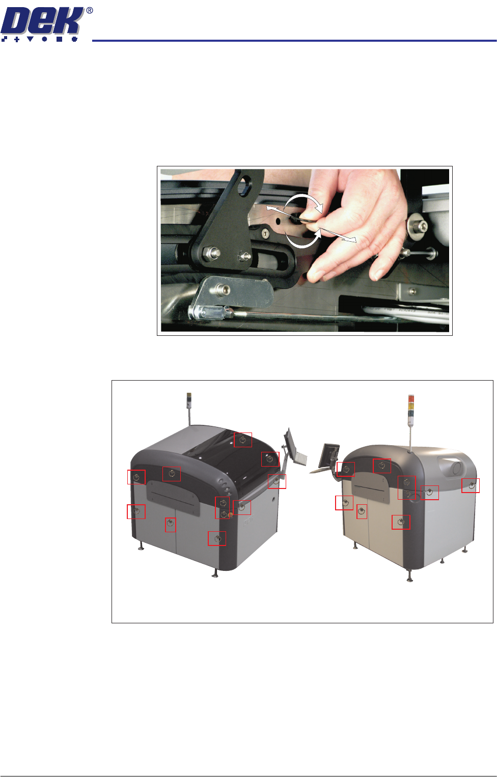
To remove a panel secured with quarter-turn ring fasteners, turn the fastener
ring anti-clockwise (-) by a quarter-turn and pull out. To refit a panel, locate the
fastener shaft into the fastener, push against the spring whilst turning the ring
clockwise a quarter turn to secure (+).
Figure 3-5 Quarter-Turn Ring Fastener
Figure 3-6 Fastener Locations
+
-
Locations (behind panels) of the Quarter Turn Ring Fasteners
COVERS
MACHINE COVERS
3.10 Technical Reference Manual Chapter Issue 2 Sep 09
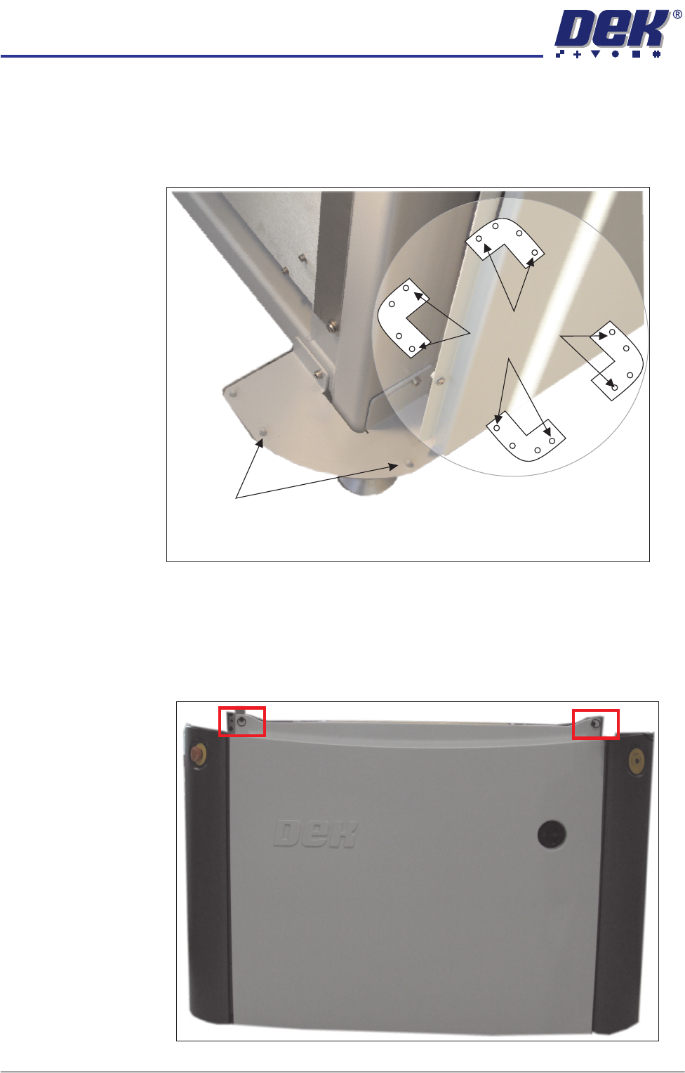
Locating Pins Side, corner, front and rear panels are secured on location pins at the base of
the machine. Plates mounted on each corner of the machine (see vignette
below) house the four pins; the two centre pins are for the corner panels and
two outer pins are for the side, front and rear panels.
Figure 3-7 Mounting Plates
Front Panel To remove the front panel, carry out the following:
1. Open the sliding glass cover.
2. Release the two quarter-turn ring fasteners located externally at the top
corners of the panel.
Corner Panel
Location Pins
View on Base of Machine
Location Pins
Side, Front &
Rear Panels