00197465-01_SM_CP20-A-M_EN.pdf - 第20页
3 Service Work Conveyor 3.2 Replacing the Component Camera 20 Service Manual SIPLACE C&P20, C&P20A, C&P20M Preparation ► Remove the head fro m the machine. For removal and installation details of the placemen…
3 Service Work Conveyor
3.1 Exchange the Placement head
Service Manual SIPLACE C&P20, C&P20A, C&P20M 19
3
3 Service Work Conveyor
Service Work Conveyor
Differenc es between CP 20/A/M
3.1
3.1 Exchange the Placement head
Exchange the Placement head
► For removal and installation details of the placement head, read the service manual for your ma
-
chine.
3.2
3.2 Replacing the Component Camera
Replacing the Component Camera
Parts, equipment and tools
▪ Component camera
Refer to the parts catalogue for the component camera item number.
▪ Torque screwdriver Torque Vario 10-60 Ncm [00386132-xx]
▪ Tools for removing the head, if needed (see also the service manual for your machine)
Overview
NOTICE
C&P20, C&P20A, C&P20M
The instructions apply in principle to all C&P20, C&P20A and C&P20M heads.
Any differences will be explicitly indicated.
► The different heads can be recognized according to the labeled stickers.
NOTICE
Additional work
► If you need to perform further work on this head (e.g. replacing spare parts), fit the head to
the head mount [03056231-xx].
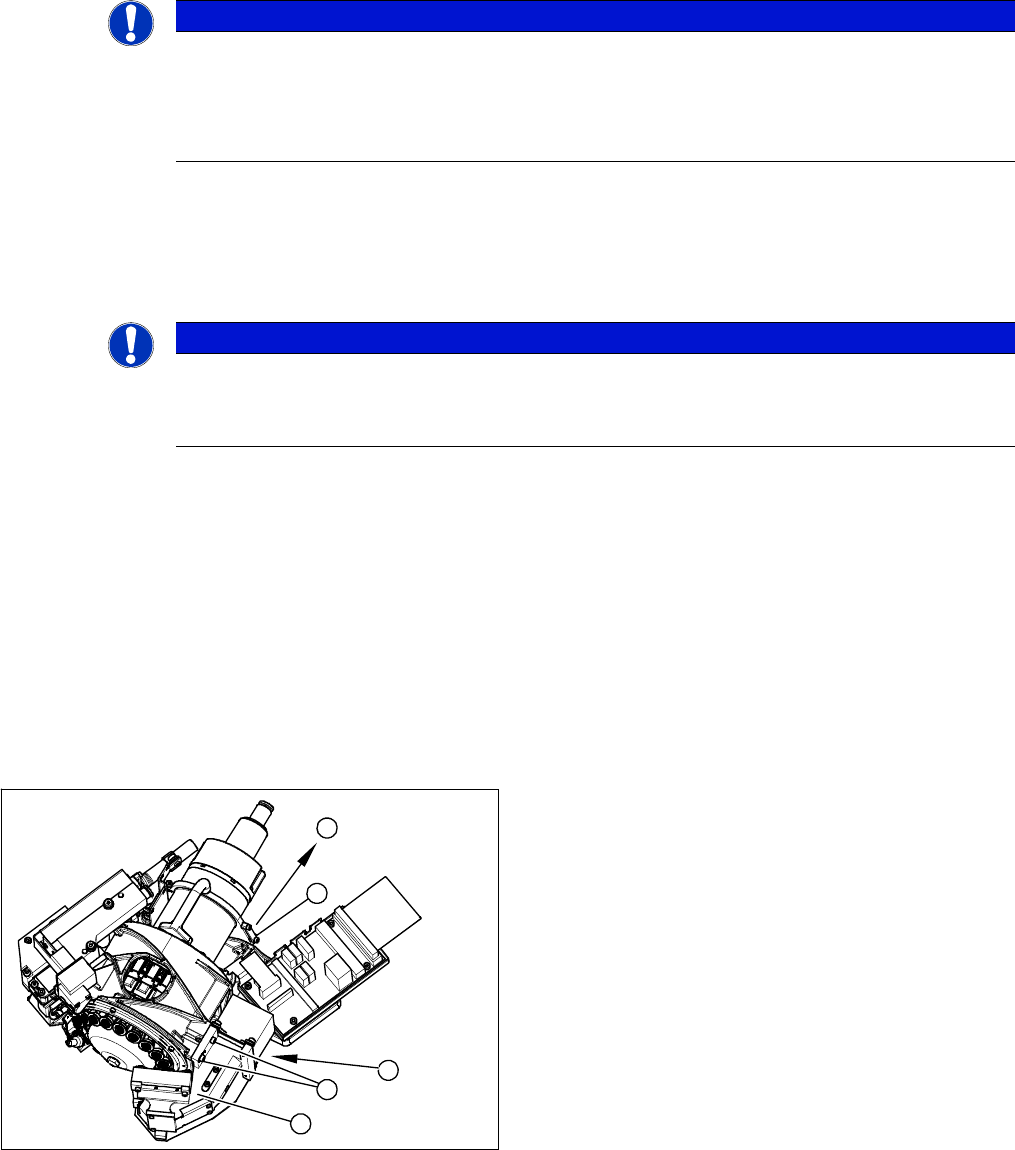
1. Component Camera
2. 4 x fastening screws on the head housing
3. To the head adapter HCU
4. Cable clamps
2
3
4
1
2
3 Service Work Conveyor
3.2 Replacing the Component Camera
20 Service Manual SIPLACE C&P20, C&P20A, C&P20M
Preparation
► Remove the head from the machine. For removal and installation details of the placement head, read
the service manual for your machine.
Removal
► Remove the cable holder for the component camera cable.
► Loosen the 4 screws fastening the component camera.
► Carefully remove the component camera from the locating pins.
Installation
► Install the new component camera. Make sure that you do not damage or contaminate the camera
lens system.
► Plug in the connection cable and fix it with cable ties, where necessary.
► Follow the removal instructions in reverse order for further installation. Also observe the following
instructions:
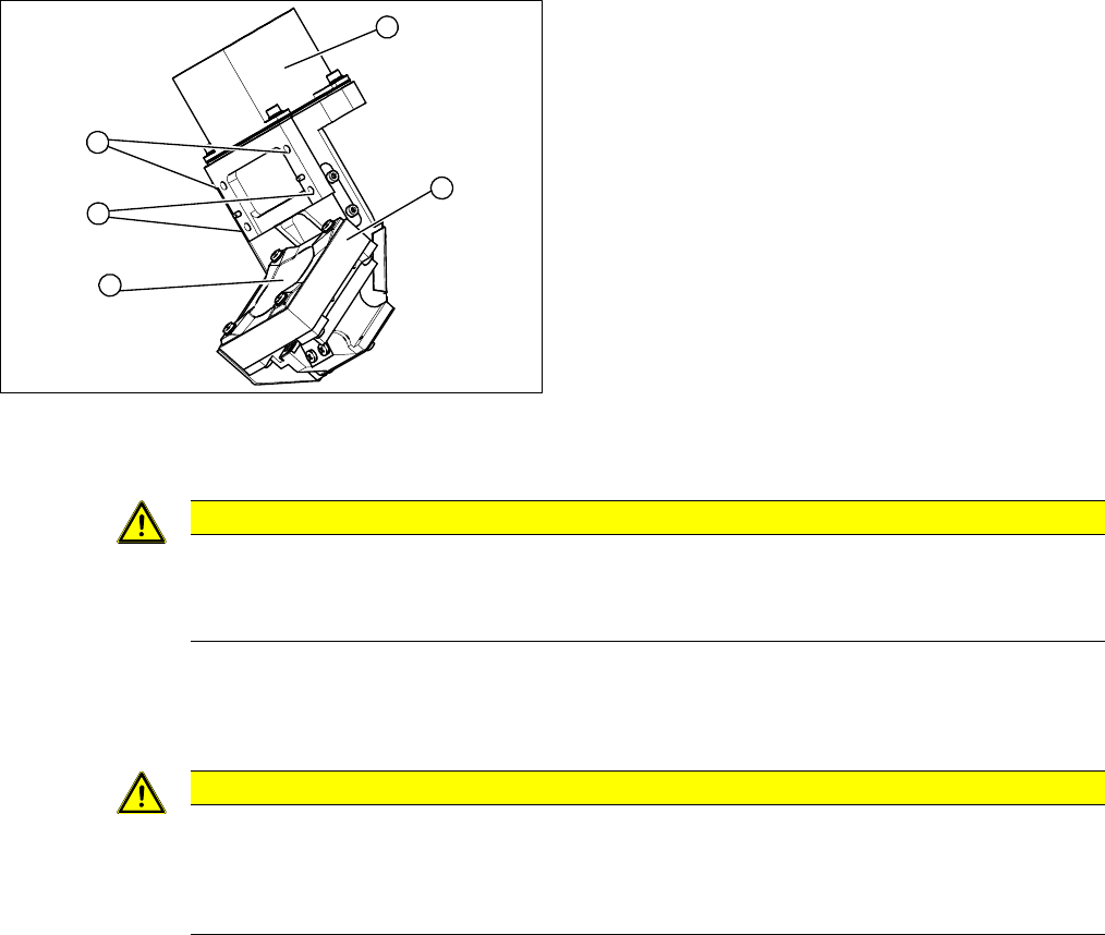
1. Component Camera
2. Camera amplifier CCD
3. 4 x fastening screws on the head housing
4. Camera lens system
3
1
4
3
2
CAUTION
Torque 1.3 Nm
Use a torque screwdriver for the fastening screws.
► Tighten the fastening screws to a torque of 1.3 Nm.
CAUTION
Installation instructions
► Calibrate the placement head. This can be done using the FHE function.
If the calibration data are stored in the camera, a brief calibration is sufficient. Otherwise,
you will have to perform a standard calibration.
3 Service Work Conveyor
3.3 Replacing the DP Drive [03058627-xx]
Service Manual SIPLACE C&P20, C&P20A, C&P20M 21
3.3
3.3 Replacing the DP Drive [03058627-xx]
Replacing the DP Drive [03058627-xx]
Parts, equipment and tools
▪ DP drive [03058627-xx] for the C&P20A
▪ Torque screwdriver Torque Vario 10-60 Ncm [00386132-xx]
▪ Dead indexing plate [03013091-xx]
▪ Tools for removing the head, if needed (see also the service manual for your machine)
Overview
Preparation
► Remove the head from the machine. For removal and installation details of the placement head, read
the service manual for your machine.
Removal
► Loosen the screw fastening the silencer and and remove the silencer.
► Loosen the three screws fastening the holding circuit.
CAUTION
Different DP drives used for CP20/CP20A!
Never use the C&P20 DP drive on the C&P20A!
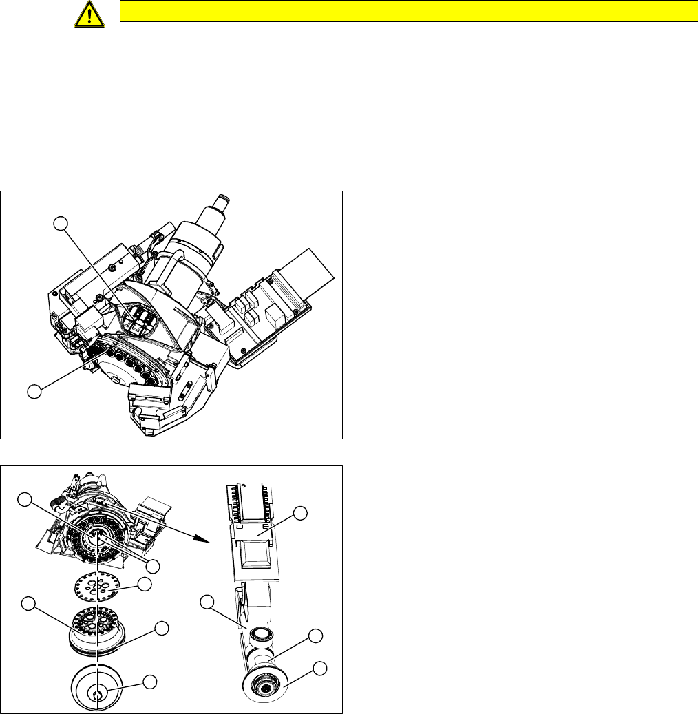
1. DP drives via the service aperture
2. Sleeves 1-20
1. Silencer
2. Hold circuit
3. O-ring
4. Seal disk
5. 3 x fastening screws on the holding circuit
6. Sleeve
7. Dead indexing plate [03013091-xx]
8. Board
9. Complete DP drive
1
2
5
6
9
8
7
1
5
4
3
2