00197465-01_SM_CP20-A-M_EN.pdf - 第29页
3 Service Work Conveyor 3.8 Replacing the Pressure Control Valve [03072785-xx] Service Manual SIPLACE C&P20, C&P20A, C&P20M 29 Preparation ► Remove the head fro m the machine. For removal and installation det…
3 Service Work Conveyor
3.8 Replacing the Pressure Control Valve [03072785-xx]
28 Service Manual SIPLACE C&P20, C&P20A, C&P20M
Installation
► Follow the removal instructions in reverse order for further installation. Also observe the following
instructions:
3.8
3.8 Replacing the Pressure Control Valve [03072785-xx]
Replacing the Pressure Control Valve [03072785-xx]
Parts, equipment and tools
▪ Pressure control valve [03072785-xx]
▪ Torque screwdriver 20-120 Ncm [00386253-xx]
▪ Tools for removing the head, if needed (see also the service manual for your machine)
Overview
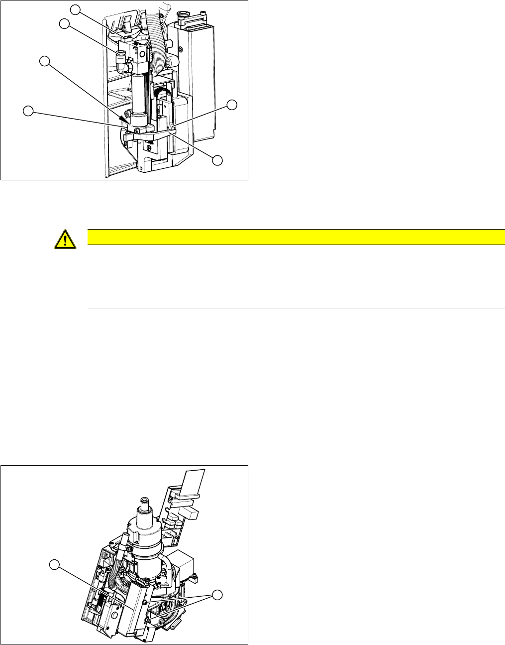
► Install the return unit with mount (2) at the stop.
► Connect the mount and tighten the two fastening
screws.
► Make sure that there is no gap (1).
► The driver (3) must touch the Z axis.
► Check that the star can be revolved.
► Check that there is a gap of approx. 0.1 mm between
the driver and the Z motor rotor (6).
► Reconnect the solenoid valve (4) connections and
the compressed air connection (5).
4
3
2
5
6
1
CAUTION
Installation instructions
► If you have loosened the screw fastening the driver, tighten it again with a torque of
1.15
Nm.
► Fi
x the cables with cable ties, where necessary.
1. Pressure control valve
2. 2 x fastening screws
The pressure control valve supplies the pickup/place
-
ment circuit with vacuum during the pickup process and
switches over to air blast during placement.
2
1
3 Service Work Conveyor
3.8 Replacing the Pressure Control Valve [03072785-xx]
Service Manual SIPLACE C&P20, C&P20A, C&P20M 29
Preparation
► Remove the head from the machine. For removal and installation details of the placement head, read
the service manual for your machine.
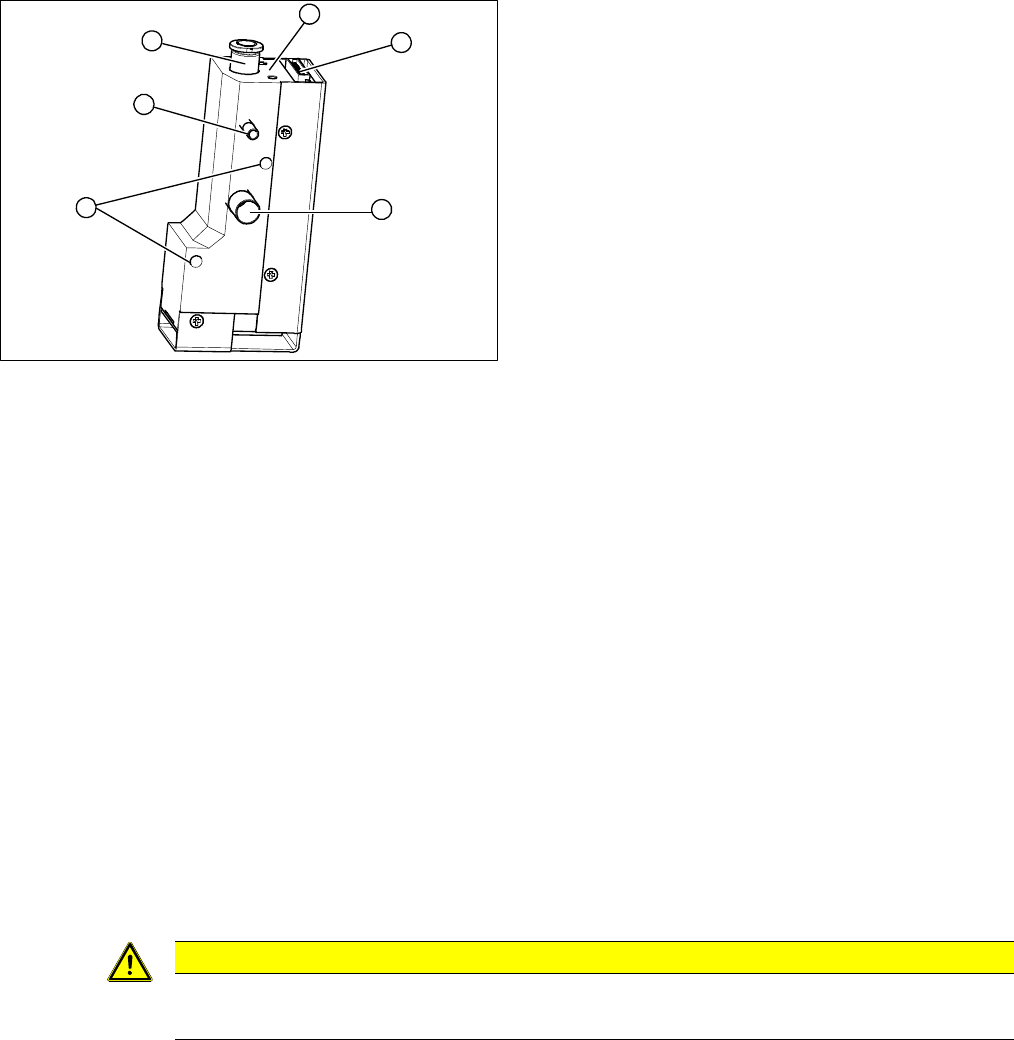
Removal
► Loosen the two screws of the strain relief and remove the energy and data supply unit.
► Open the cable clamp fastening the cable to the component camera.
► Disconnect the hoses for compressed air, vacuum/blast air and exhaust air.
► Loosen the two fastening screws on the pressure control valve and remove the pressure control
valve.
Installation
► Fit the new pressure control valve. Tighten the screws fastening the pressure control valve with a
torque of 90 Ncm.
► Reconnect to the electrical and compressed air systems.
► Follow the removal instructions in reverse order for further installation. Also observe the following
instructions:
1. Strain relief with intermediate plate
2. Energy and data supply.
3. Compressed air connection
4. Vacuum/air blast for pickup/placement circuit
5. Exhaust air, for cooling the X linear motor
6. Fastening screws for pressure control valve
1
6
5
4
3
2
CAUTION
Installation instructions
► Perform "zero correction" for the pressure control valve.
3 Service Work Conveyor
3.9 Replacing the intermediate distributor board [03002942-xx] on the C&P20A head
30 Service Manual SIPLACE C&P20, C&P20A, C&P20M
3.9
3.9 Replacing the intermediate distributor board [03002942-xx] on the C&P20A head
Replacing the intermediate distributor board [03002942-xx] on
the C&P20A head
Parts, equipment and tools
▪ Intermediate distributor board C&P [03002942-xx]
▪ Tools for removing the head, if needed (see also the service manual for your machine)
Overview
Preparation
► Although this work can be performed in the machine, you might find it advisable to remove the head
so that you have better access to it. For removal and installation details of the placement head, read
the service manual for your machine.
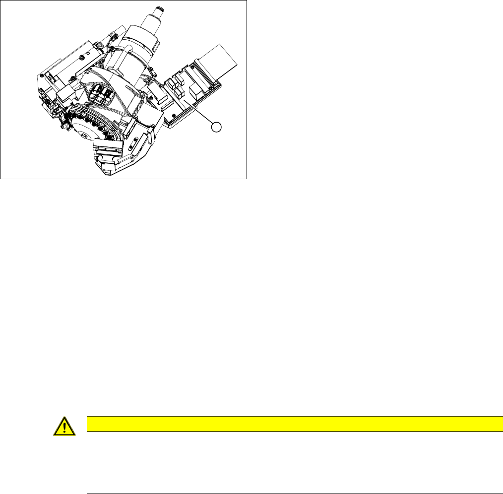
Removal
► Number the cable connections:
Make sure you do not confuse the connectors for the track signals!
► Remove the connectors from the intermediate distributor.
► Loosen the 4 fastening screws and remove the intermediate distributor.
Installation
► Follow the removal instructions in reverse order for installation. Also observe the following instruc
-
tions:
See also
5.6.1 Transmitting the Head-Specific Data (from SW601) [ ➙ 63]
1. Intermediate distributor
1
CAUTION
Installation instructions
Transfer the machine data to the EPROM!
► Transfer the machine data from the station to the intermediate distributor. Read section "5.6
Transferring the head specific data" [ ➙ 63].