00197465-01_SM_CP20-A-M_EN.pdf - 第31页
3 Service Work Conveyor 3.10 Replacing and Setting the Jaws [03010313-xx] Service Manual SIPLACE C&P20, C&P20A, C&P20M 31 3.10 3 . 1 0 R e p la c in g a n d S e t t in g t h e J a w s [ 0 3 0 1 0 3 1 3 - x x …
3 Service Work Conveyor
3.9 Replacing the intermediate distributor board [03002942-xx] on the C&P20A head
30 Service Manual SIPLACE C&P20, C&P20A, C&P20M
3.9
3.9 Replacing the intermediate distributor board [03002942-xx] on the C&P20A head
Replacing the intermediate distributor board [03002942-xx] on
the C&P20A head
Parts, equipment and tools
▪ Intermediate distributor board C&P [03002942-xx]
▪ Tools for removing the head, if needed (see also the service manual for your machine)
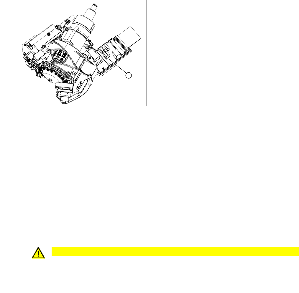
Overview
Preparation
► Although this work can be performed in the machine, you might find it advisable to remove the head
so that you have better access to it. For removal and installation details of the placement head, read
the service manual for your machine.
Removal
► Number the cable connections:
Make sure you do not confuse the connectors for the track signals!
► Remove the connectors from the intermediate distributor.
► Loosen the 4 fastening screws and remove the intermediate distributor.
Installation
► Follow the removal instructions in reverse order for installation. Also observe the following instruc
-
tions:
See also
5.6.1 Transmitting the Head-Specific Data (from SW601) [ ➙ 63]
1. Intermediate distributor
1
CAUTION
Installation instructions
Transfer the machine data to the EPROM!
► Transfer the machine data from the station to the intermediate distributor. Read section "5.6
Transferring the head specific data" [ ➙ 63].
3 Service Work Conveyor
3.10 Replacing and Setting the Jaws [03010313-xx]
Service Manual SIPLACE C&P20, C&P20A, C&P20M 31
3.10
3.10 Replacing and Setting the Jaws [03010313-xx]
Replacing and Setting the Jaws [03010313-xx]
Parts, equipment and tools
▪ Jaws [03010313-xx] (only for replacement of jaws)
▪ Kit for setting C&P20 jaws [03058847-xx]
This contains the following items:
– Jaw setting gauge for C&P20 [03045455-xx] (incl. 2x hexagonal socket-head screw
M2.5x12 mm)
– 10x feeler gauge 0.01 mm [03058840-xx]
– 5x feeler gauge 0.04 mm [03058839-xx]
– Silicon hose D12, length 20 mm [03058392-xx]
– Protective hose for C&P20 component sensor [03078596-xx]
– 10x dead indexing plate [03013091-xx]
– 2x oval head screw DIN7985-M2x4-A2-Z [00304612-xx]
▪ Phillips screwdriver with torque limiter, set to 35 Ncm
▪ Head mounting rack [03056231-xx]
▪ Hexagon socket-head wrench
▪ Magnet removal plate C&P20A [03078491-xx]
▪ Tools for removing the head, if needed (see also the service manual for your machine)
Basic instructions for setting the jaws
The jaws need to be correctly set, to ensure that the bridge between the raceway and jaws is accurate.
The correct height between the raceway and jaws is achieved by determining the zero point correction
value for the Z axis.
When fitting the jaws at the Z axis, it is possible to rotate the jaws. With the help of the jaw setting gauge,
the correct angle of the jaws to the raceway can be fixed.
When do you need to set the jaws?
▪ When replacing the light barrier down, check the position of the jaws with the station software.
▪ When fitting the new Z axis drive.
▪ When error messages are issued by the station software (e.g. reference run).
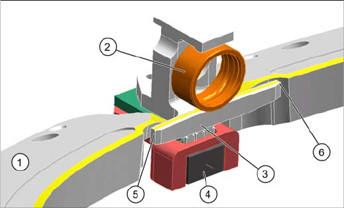
Raceway with Z axis
1. Raceway
2. Ball bearing on segment
3. Snap jaws
4. Light barrier down
5. Bridge raceway – jaws, left
6. Bridge raceway – jaws, right
3 Service Work Conveyor
3.10 Replacing and Setting the Jaws [03010313-xx]
32 Service Manual SIPLACE C&P20, C&P20A, C&P20M
Overview
Preparation
► Remove the head from the machine. For removal and installation details of the placement head, read
the service manual for your machine.
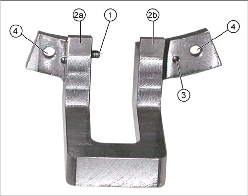
Jaw setting gauge
1. Side stop for jaws
2. 2a and 2b: contact surfaces for jaws
3. Centering pins for accurate setting to raceway
4. Gauge fixture on raceway (screws --> M2.5x12 mm)