00197465-01_SM_CP20-A-M_EN.pdf - 第34页
3 Service Work Conveyor 3.10 Replacing and Setting the Jaws [03010313-xx] 34 Service Manual SIPLACE C&P20, C&P20A, C&P20M ► Use the magnet removal plate (1) to remove the two magnets (3) . CAUTION! If the mag…
3 Service Work Conveyor
3.10 Replacing and Setting the Jaws [03010313-xx]
Service Manual SIPLACE C&P20, C&P20A, C&P20M 33
Replacing and setting the jaws
Perform the following preparatory tasks.
NOTICE
Replace or set the jaws?
The procedure for replacing and setting the jaws is almost identical. Any differences will be ex
-
plicitly indicated.
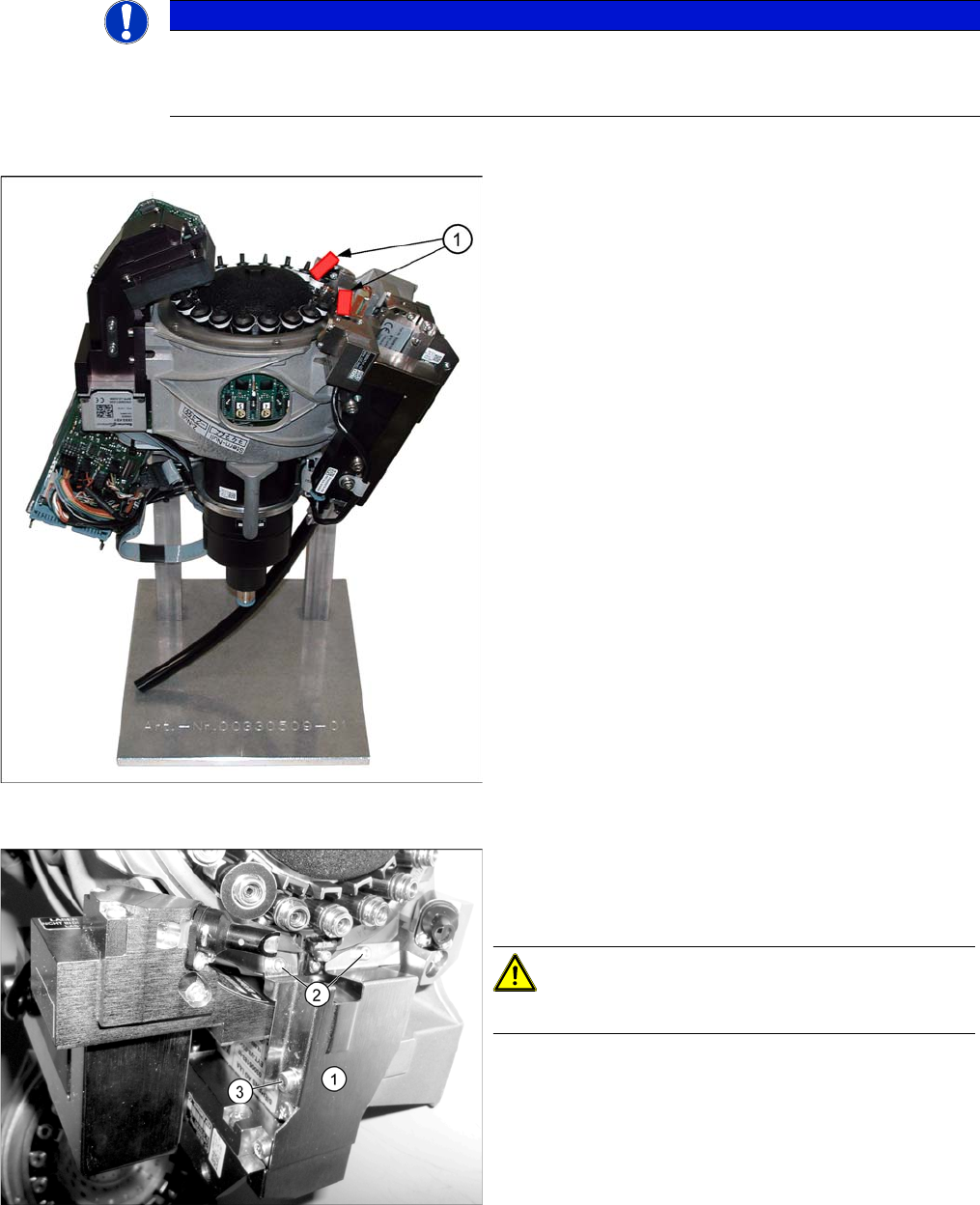
C&P20 placement head on placement head base
► To protect the component sensor, fit the red rubber
hose (1) (length approx. 20 mm)onto the component
sensor prisms. (Cut the rubber hose into two 20 mm
pieces.)
► Remove the head from the machine. (See Replacing
the C&P20A Head)
► Fit the placement head onto the head rack
[00330509-01] (see diagram).
Dismantling the Z axis cover
► Dismantle the cover plate (1) over the Z axis. Loosen
the screws at (2) and (3). Carefully remove the cover
plate.
CAUTION!
Take care not to damage the component sensor prisms.
► Fasten the Z motor unit back into place with the orig
-
inal screw (3). This ensures that the Z motor unit is in
the exact position. This is required for setting the
jaws.
3 Service Work Conveyor
3.10 Replacing and Setting the Jaws [03010313-xx]
34 Service Manual SIPLACE C&P20, C&P20A, C&P20M
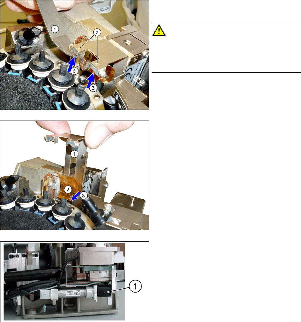
► Use the magnet removal plate (1) to remove the two
magnets (3).
CAUTION!
If the magnets are stuck in place, you can press these out
from above (2) with a pointed object. If you damage the
foil while removing the magnets, you will need to also re
-
place the foil.
► Pull out the plate (1).
► Loosen the screw (3) fastening the foil (2) and then
remove the foil.
Fitting the hose piece onto the return unit
► Clamp the black hose piece D12 20 mm (1) from the
service pack between the actuator and the housing of
the return unit.
This ensures that the Z axis can still be moved for lat
-
er adjustment and the return unit does not need to be
dismantled.
3 Service Work Conveyor
3.10 Replacing and Setting the Jaws [03010313-xx]
Service Manual SIPLACE C&P20, C&P20A, C&P20M 35
Dismantling the dead indexing plate
1. 2 segments without nozzles or dead indexing plate
► Remove the nozzles and dead indexing plates from
two neighboring segments.
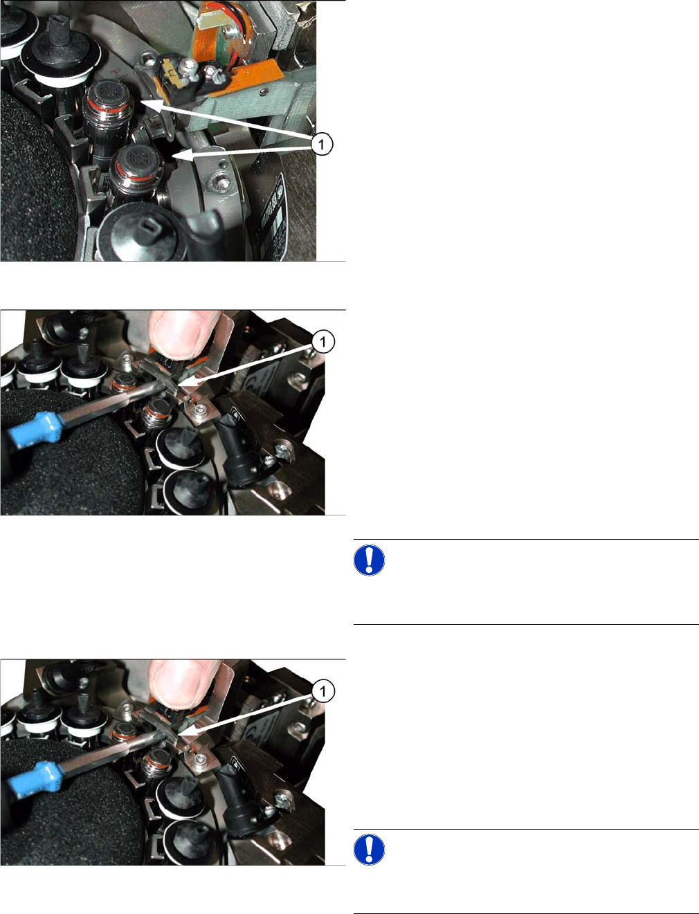
Screw fastening the jaws
Perform the following steps if you want to replace the
jaws (and then set them).
► Loosen the screw (1) fastening the jaws and then pull
the jaws out of the head.
► Insert the new jaws. Carefully tighten the screw fas
-
tening the jaws, so that the jaws can still be moved on
the arm of the Z axis (can be moved to the left and
right).
Do not fit the gauge yet!
► Clean the raceway contact surface and the setting
gauge with a lint-free cloth.
NOTICE!
Always clean the contact surfaces before fitting the set
-
ting gauge!
Screw fastening the jaws
Perform the following steps if you want to set the jaws
without replacing them.
► Carefully loosen the screw (1) fastening the jaws, so
that the jaws can still be moved on the arm of the Z
axis (can be moved to the left and right).
Do not fit the gauge yet!
► Clean the raceway contact surface and the setting
gauge with a lint-free cloth.
NOTICE!
Always clean the contact surfaces before fitting the set
-
ting gauge!