00197465-01_SM_CP20-A-M_EN.pdf - 第38页
3 Service Work Conveyor 3.10 Replacing and Setting the Jaws [03010313-xx] 38 Service Manual SIPLACE C&P20, C&P20A, C&P20M ► Place a 0.04 mm fee ler gauge b etween the jaws and th e side stop in the jaw settin…
3 Service Work Conveyor
3.10 Replacing and Setting the Jaws [03010313-xx]
Service Manual SIPLACE C&P20, C&P20A, C&P20M 37
Set the jaws as follows:
► Make sure that the Z axis is located between the two segments without dead indexing plates and
that you can see the Phillips screw.
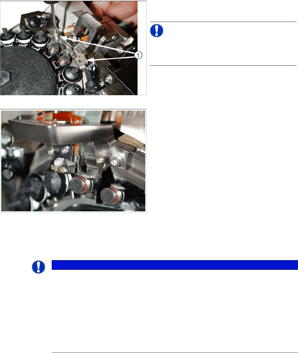
Fastening the jaw setting gauge
Jaw setting gauge on C&P20 head
► Fasten the gauge with the screws (1) from the service
kit (M2.5x12 mm).
NOTICE!
Do not use the original raceway screws, to fix the jaw set
-
ting gauge! These are too short and could damage the
thread!
NOTICE
Troubleshooting:
► If side stopper (stop pin) of the gauge presses against the jaws so that these can not be
moved, proceed as follows:
if it is not possible to push the 0.04 feeler gauge between the jaws and the stop pin of the
gauge, make sure that the jaws lie flat against contact surfaces (2a) and (2b) of the gauge
(see overview picture at the beginning of this chapter.)
► If you are unable to press the jaws against the side stopper (stop pin) of the gauge, proceed
as follows:
push the jaws as far as possible towards the stop pin. Do not push the jaws with force
against the stop pin of the gauge.
3 Service Work Conveyor
3.10 Replacing and Setting the Jaws [03010313-xx]
38 Service Manual SIPLACE C&P20, C&P20A, C&P20M
► Place a 0.04 mm feeler gauge between the jaws and the side stop in the jaw setting gauge.
► Move the jaws so that they are against the two contact surfaces and the side stop (stop pin) + feeler
gauge.
► Hold the jaws in this position and tighten the Phillips screw with the torque wrench (torque 35 Ncm)
(see next diagram).
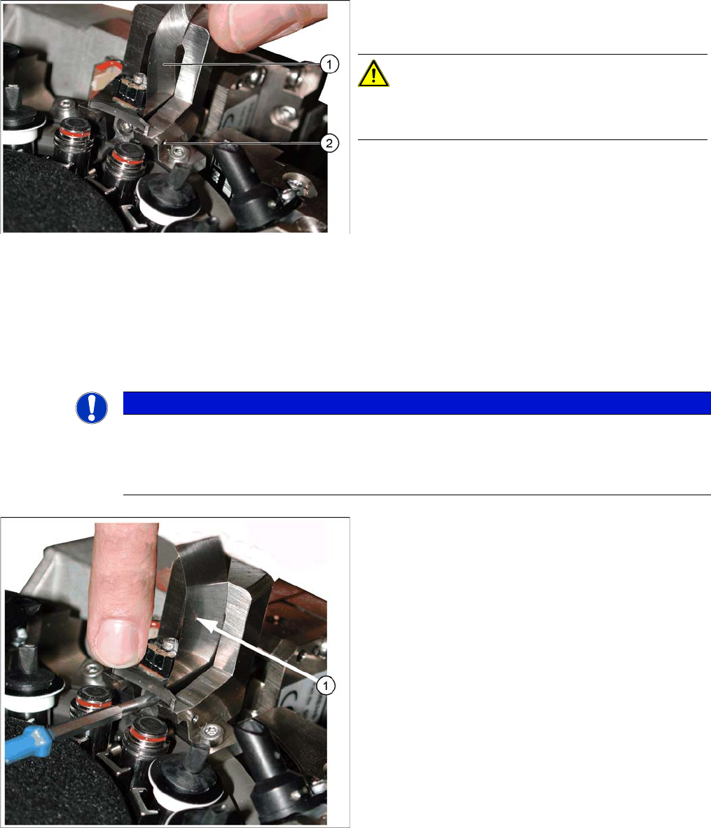
Correct setting with feeler gauge
1. Feeler gauge 0.04 mm
2. Stop pin (drilling for pin, view from outside)
CAUTION!
The stop pin is fixed with adhesive.
Do not adjust the stop pin.
NOTICE
Snap jaws
Make sure that the jaws lie flat against the contact surfaces and the side stop and do not turn.
Use the 0.01 feeler gauge to check that the jaws are really against the contact surfaces of the
gauge (through own weight).
Tightening the screws fastening the jaws
► Pull out the feeler gauge (1) and test with the 0.01
feeler gauge. This should fit easily between the stop
pin and the jaws.
► Carefully tip the jaw setting gauge to remove it, with
-
out hitting the jaws.
► Feed the segment ball bearing back into the Z axis
jaws.
3 Service Work Conveyor
3.10 Replacing and Setting the Jaws [03010313-xx]
Service Manual SIPLACE C&P20, C&P20A, C&P20M 39
Final Work:
Further installation is performed by following the above instructions in the reverse order. Proceed as fol
-
lows:
► Attach the two new dead indexing plates (not the ones you removed, these could be damaged). At
-
tach nozzles, if required.
► Remove the hose piece from the return unit.
► Refit the Z axis cover.
► Fit the remaining parts and install the head in the machine.
► Connect all cables and hoses.
► Switch the placement machine on.
► Determine the zero point correction value for the star and Z axes.
See also
5.4.3 Determining the zero point correction value for the star and Z axis from SW605.03.SP1 [ ➙ 57]
5.4.4 Determining the Zero Point Correction Value for the Star and Z Axis from SW705.04 [ ➙ 58]