00197465-01_SM_CP20-A-M_EN.pdf - 第45页
3 Service Work Conveyor 3.12 Replacing the Z Drive [03058631-xx] Service Manual SIPLACE C&P20, C&P20A, C&P20M 45 ► Reconnect to the electricity sy stem. Fasten the cable with cab le ties. ► Fit the Z drive un…
3 Service Work Conveyor
3.12 Replacing the Z Drive [03058631-xx]
44 Service Manual SIPLACE C&P20, C&P20A, C&P20M
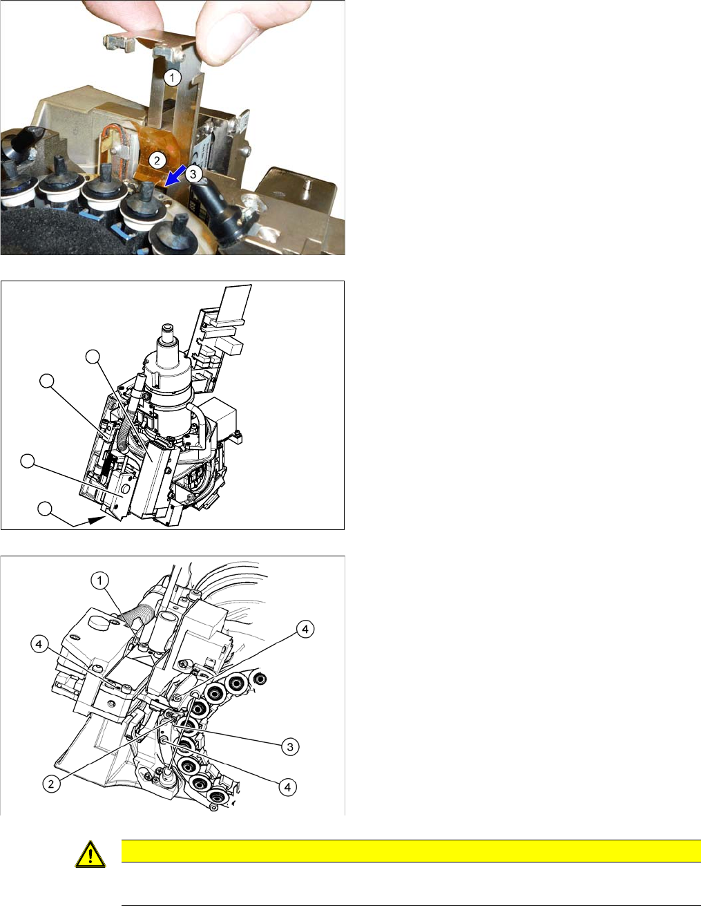
► Pull out the plate (1).
► Loosen the screw (3) fastening the foil (2) and then
remove the foil.
► Remove the pressure control valve (1). This gives
you access to the Z drive.
► Loosen the two screws fastening the return unit (2)
and unplug the electrical supply at the solenoid valve
and the hose at the compressed air connection.
► Remove the complete return unit (2).
► Remove the nozzles and dead indexing plates from
two neighboring segments. This makes it easier to
unthread the Z drive.
► Loosen the screw (1) fastening the Z drive.
► Rotate the star into its central position.
► Move the Z drive downwards and unthread the snap
jaws (2) from the ball bearings (3) of the DP drive.
1
3
2
4
CAUTION
Check how the cables are run!
Make sure that you do not touch or damage the flex cable.
3 Service Work Conveyor
3.12 Replacing the Z Drive [03058631-xx]
Service Manual SIPLACE C&P20, C&P20A, C&P20M 45
► Reconnect to the electricity system. Fasten the cable with cable ties.
► Fit the Z drive unit. While fastening the screws, push this unit against the stopper. (Torque 130 Ncm).
► Fit the return unit and the pressure control valve.
► Remove the cable ties and unplug the cable from the
intermediate distributor.
⇨ Track signals incremental encoder
⇨ Light barrier down
⇨ Linear motor
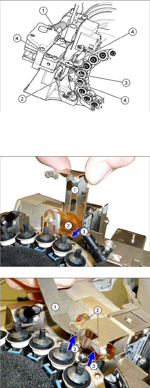
► Thread the jaws (2) of the new Z axis in at the DP
drive ball bearing (3). The snap jaws must engage.
► Fix the foil (2) into place by tightening the screw (3).
► Insert the plate (1).
► Thread the foil into the plate and reinsert the magnets
(3). The magnets hold the foil in place.
3 Service Work Conveyor
3.12 Replacing the Z Drive [03058631-xx]
46 Service Manual SIPLACE C&P20, C&P20A, C&P20M
► Follow the removal instructions in reverse order for further installation.
► Start the station software and perform zero point correction by means of a reference run (SW60x) or
via the manual operations for the head (SW70x).
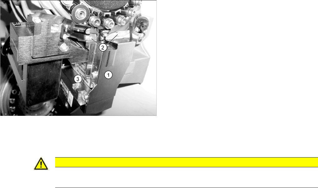
► Fit the cover plate (1). Screw in and tighten the
screws at (2) until hand-tight and then tighten the
screw at (3) with a torque of 130 Ncm.
CAUTION
Reference run reports error
► If the reference run fails, you will need to check the settings for the jaws on the Z drive.