00197465-01_SM_CP20-A-M_EN.pdf - 第54页
5 Settings 5.4 Zero Point Correction for the Star and Z Axis 5.4.1 Transfer head specific data to the machine data after manual head 54 Service Manual SIPLACE C&P20, C&P20A, C&P20M 5.4 5 . 4 Z e r o P o in t …
5 Settings
5.3.1 Calibrating the Heads and Cameras 5.3 Calibration
Service Manual SIPLACE C&P20, C&P20A, C&P20M 53
5.3.1
5.3.1 Calibrating the Heads and Cameras
Calibrating the Heads and Cameras
5.3.2
5.3.2 Calibration Procedure (C&P, CPP, DLM)
Calibration Procedure (C&P, CPP, DLM)
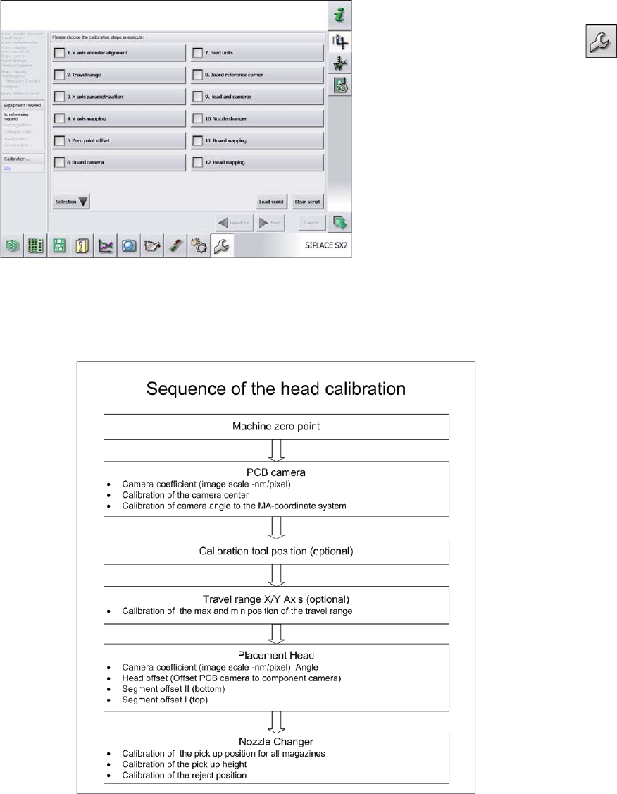
C&P calibration procedure
► Switch over to the operator level Service (Customer).
► Switch over to the Service menu and select Ma
-
chine calibration or Automatic calibration (depending
on SW version).
► Select 8. Head and cameras and click on Next.
► On the next page, select the gantries on which the
heads to be calibrated are located and then click on
Next.
► The next step is to check the calibration conditions
(nozzle, calibration tool etc.). Follow the instructions
provided.
After this step, calibration will begin. All required interme
-
diate steps (head height etc.) will be performed automat
-
ically.
5 Settings
5.4 Zero Point Correction for the Star and Z Axis 5.4.1 Transfer head specific data to the machine data after manual head
54 Service Manual SIPLACE C&P20, C&P20A, C&P20M
5.4
5.4 Zero Point Correction for the Star and Z Axis
Zero Point Correction for the Star and Z Axis
5.4.1
5.4.1 Transfer head specific data to the machine data after manual head exchange
Transfer head specific data to the machine data after manual head exchange
Transfer head specific data manually
Precondition: The head needs to have been referenced (star and Z axis).
NOTICE
Fast Head Exchange
If a head exchange is carried out with the FHE function the head specific data will be automat
-
ically transferred to the machine data.
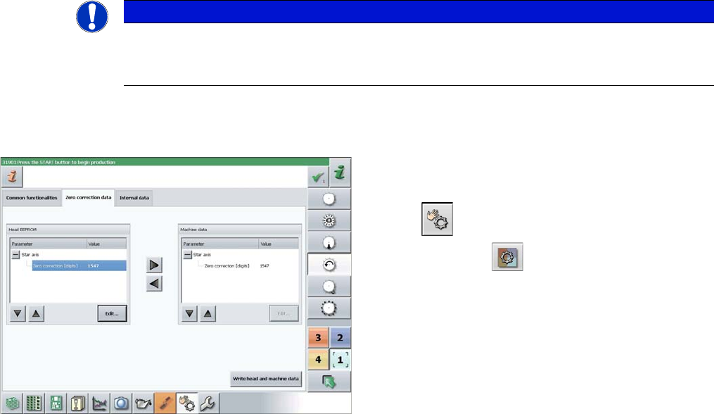
► Switch over to operator level SIPLACE (customer).
► Select Manual operations (Check sensors and func
-
tions) --> Check sensors and functions of spe
-
cific components .
► Select the relevant head.
► Select Z axis.
► Select Zero correction data.
► In the Head EEPROM section, select the relevant pa
-
rameters, then click on Edit and enter the corre
-
sponding value.
► Use the arrow button of the head EEPROM to trans
-
fer the data to the machine data.
► After correcting the parameters, select Write head
and machine data.
► Repeat these settings for the star axis.
5 Settings
5.4.2 Determination of Z and Star axes zero point correction (SITEST) 5.4 Zero Point Correction for the Star and Z Axis
Service Manual SIPLACE C&P20, C&P20A, C&P20M 55
5.4.2
5.4.2 Determination of Z and Star axes zero point correction (SITEST)
Determination of Z and Star axes zero point correction (SITEST)
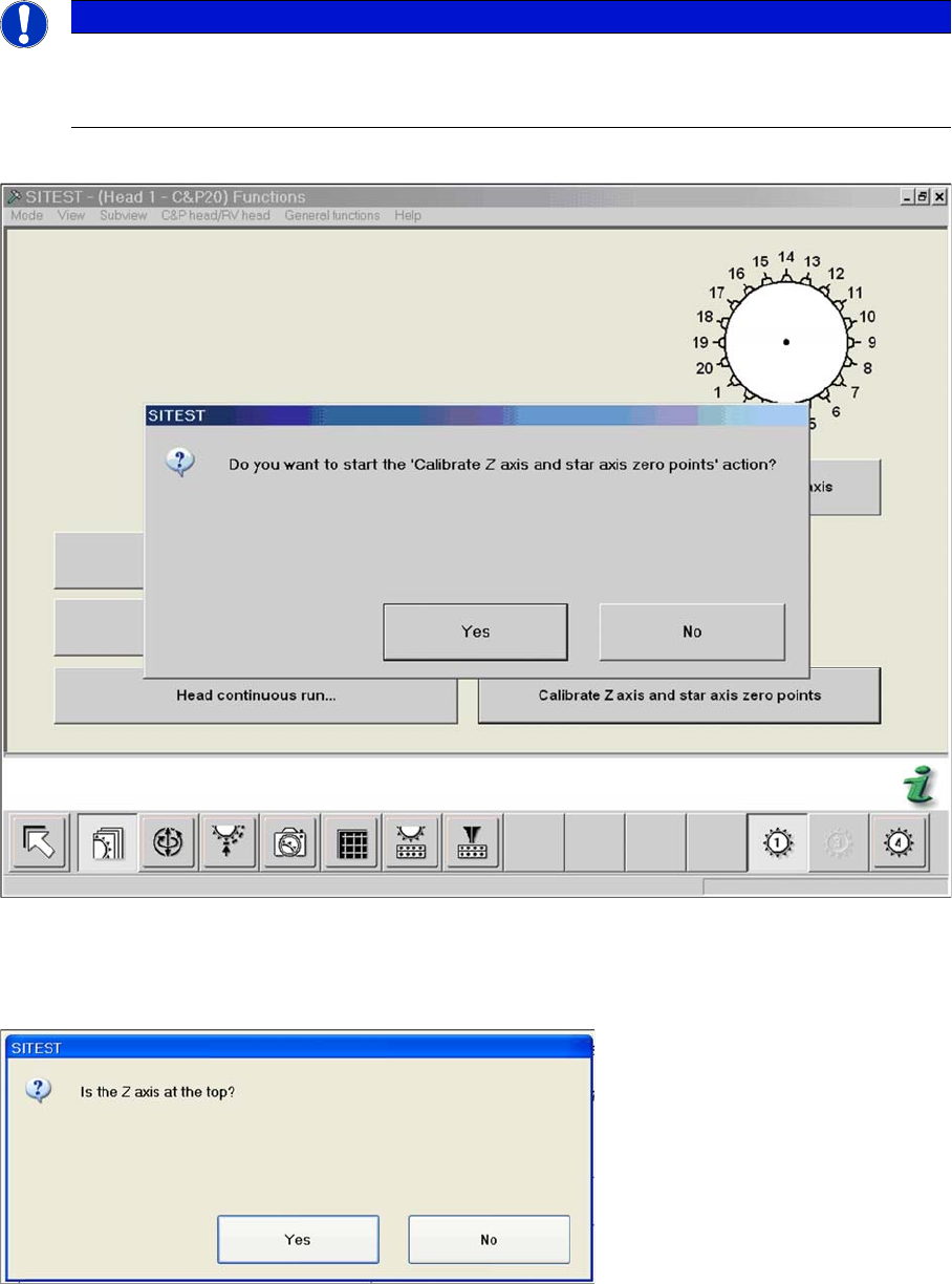
► Start SITEST --> Head Functions .
The zero point corrections has to be determined again after service work on the Z axis or star axis.
► Click on the Calibrate Z axis and star axis zero points button.
► Confirm the question shown with YES.
► Check the position of the Z axis and click on YES.
NOTICE
After service work at C&P20
The function Calibrate zero point correction should be carried out after service work to the
C&P20 head.