00197465-01_SM_CP20-A-M_EN.pdf - 第60页
5 Settings 5.4 Zero Point Correction for the Star and Z Axis 5.4.4 Determin ing the Zero Point Correction Value for the Star and Z Axis fro m 60 Service Manual SIPLACE C&P20, C&P20A, C&P20M Troubleshooting - …
5 Settings
5.4.4 Determining the Zero Point Correction Value for the Star and Z Axis from SW705.04 5.4 Zero Point Correction for the Star and Z Axis
Service Manual SIPLACE C&P20, C&P20A, C&P20M 59
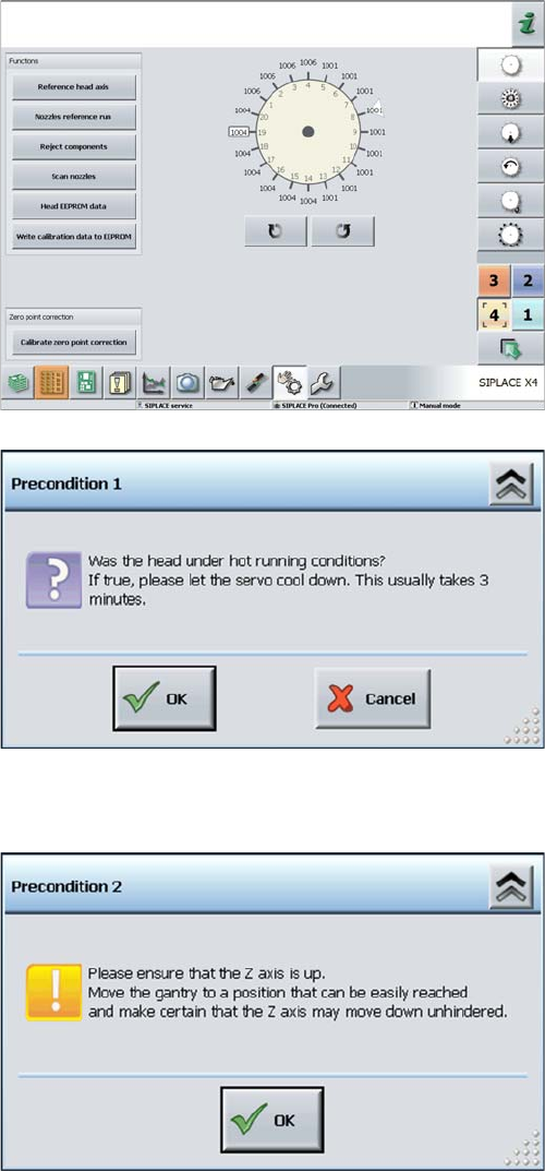
► Select the relevant head.
► Click on the Calibrate Z axis and star axis zero points
button.
Calibrating the Z axis and star axis zero point correction
values
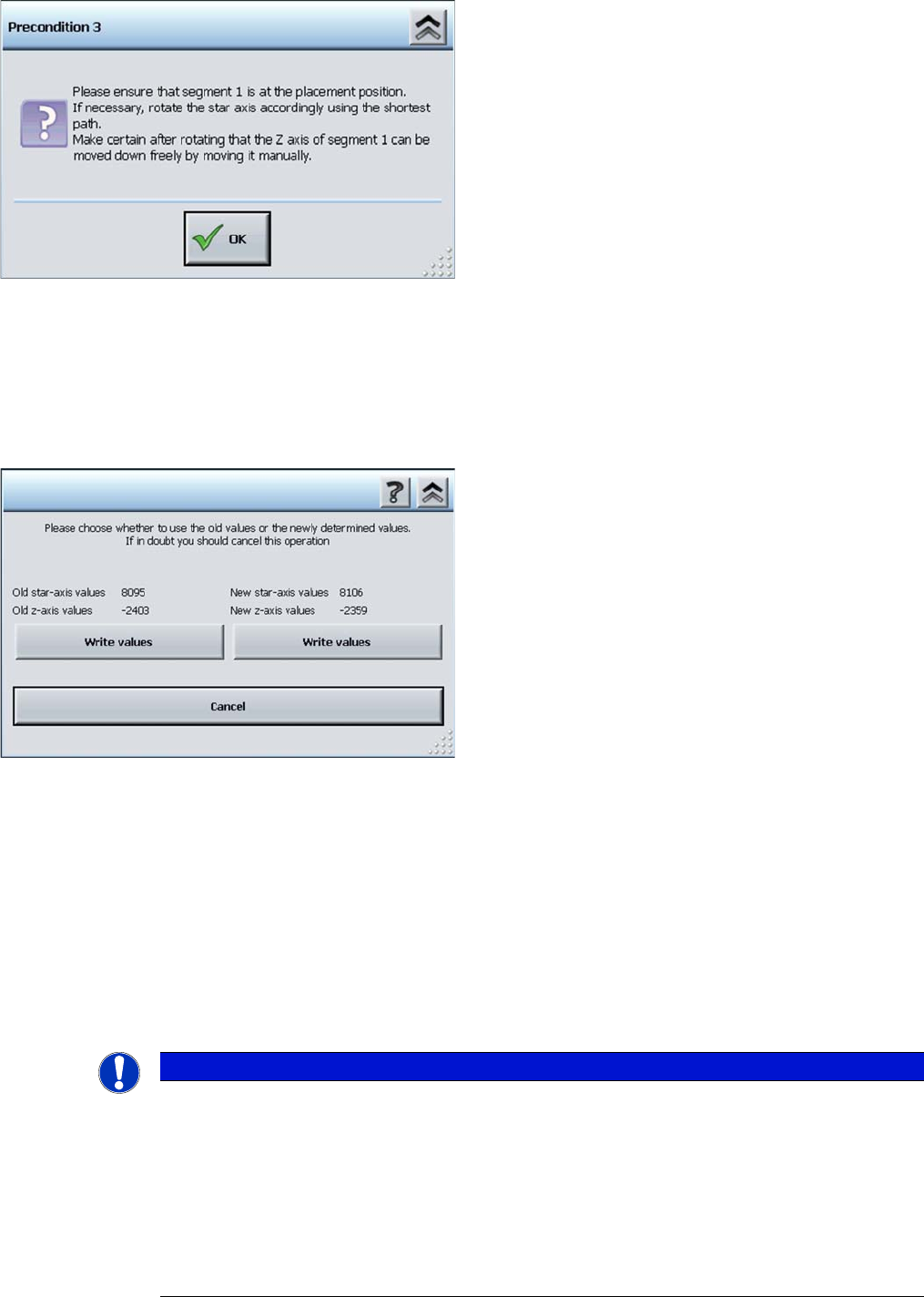
► You may need to wait 3 minutes, until the head has
cooled down.
► Acknowledge the question shown with OK.
Z axis up request for confirmation
► Check the position of the Z axis and click on OK.
5 Settings
5.4 Zero Point Correction for the Star and Z Axis 5.4.4 Determining the Zero Point Correction Value for the Star and Z Axis from
60 Service Manual SIPLACE C&P20, C&P20A, C&P20M
Troubleshooting - calibration of zero point correction
If calibration was not successful:
1. Check the Z axis path.
The max. and min. travel of the Z axis (C&P20) is 34000 digits and -200 digits.
2. Error message: FM 19127 – Values calculated for the zero point correction exceed the tolerance lim
-
its.
This means that the angle of the Z axis is outside the threshold values.
Solution: Use the setting gauge to set the jaws on the C&P20 head.
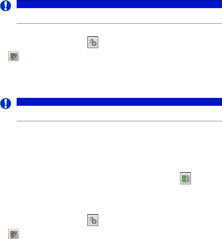
Turning segment 1 manually into the placement position
► Rotate the star with segment 1 by the shortest route,
into the placement position.
► Open the cover.
► Rotate the star until segment 6 can be seen through
the service opening. Segment 1 is then in the pick
and place position.
► Move segment 1 downwards with the help of the re
-
turn unit.
► When the segment is moved out (Z axis down), check
that the segment ball bearing is in the center of the
jaws.
► Close the cover.
► Press the Start button on the machine.
► Click on OK on your screen.
The calibration process will begin and the new Z axis and
star axis zero point correction values will be calculated.
Display showing old and new values
► If the new values are plausible, click on the right-hand
button Write values under the new values.
NOTICE
Other solutions
If the jaws have already been set, proceed as follows:
► Dismantle the placement head as described above and fit the setting gauge, without loos
-
ening the screw fastening the jaws beforehand.
► Use the 0.01 mm feeler gauge to check whether the jaws are really placed against the con
-
tact surfaces 2a and 2b. If this is the case, loosen the screw fastening the jaws and place
two 0.01 mm feeler gauges between the jaws and contact surface 2a, so that they are just
clamped in between the jaws and the setting gauge.
5 Settings
5.5.1 Zero Point Calibration of Pressure Control Valve 5.5 Calibrating the Digital Pressure Control Valve
Service Manual SIPLACE C&P20, C&P20A, C&P20M 61
5.5
5.5 Calibrating the Digital Pressure Control Valve
Calibrating the Digital Pressure Control Valve
The digital pressure control valve is part of the placement head and generates the vacuum and the air
kiss for the pick and place functions. The zero point correction for the digital pressure control valve needs
to be checked when first put into operation at the customer site. It also needs to be checked and possibly
recalibrated after the digital pressure control valve or placement head has been replaced.
If you do not calibrate the pressure control valve, incorrect threshold values will be taken to calculate "No
component on the nozzle?" or "Nozzle is dirty".
The zero point calibration is used to set the motor in the digital pressure control valve into a neutral or
central position so that there is no vacuum or air blast at the nozzle.
5.5.1
5.5.1 Zero Point Calibration of Pressure Control Valve
Zero Point Calibration of Pressure Control Valve
► Switch over to operator level SIPLACE (customer).
► Select Check sensors and functions --> Check sensors and functions of specific components
.
► Select the head (TwinHead).
► Select Check vacuum functions --> Specialized --> Zero pressure adjustment.
5.5.2
5.5.2 Calibrating the Closed Vacuum
Calibrating the Closed Vacuum
Parts, equipment and tools
▪ Calibration nozzle 518
Calibration
► Place the calibration nozzle for the Twin head by hand on the sleeve of the appropriate P&P module.
Make sure that the two sleeve adjust pins fit correctly into the nozzle.
► Select Locations (display, check and set up feeders, components and nozzles) .
► Select the relevant head.
► Click on Set another nozzle..., select the 516 nozzle and then click on OK.
► Switch over to operator level SIPLACE (customer).
► Select Check sensors and functions --> Check sensors and functions of specific components
.
► Select the relevant head.
► Select Vacuum functions --> Specialized --> Calibrate vacuum with closed nozzle.
NOTICE
From SW706
This function is performed automatically from SW706 (Menu Automatic calibration).
NOTICE
From SW706
This function is performed automatically from SW706 (Menu Automatic calibration).