00197465-01_SM_CP20-A-M_EN.pdf - 第62页
5 Settings 5.5 Calibrating the Digital Pre ssure Control Valve 5.5.3 Checkin g the Pressure Tightness of the Vacuum System 62 Service Manual SIPLACE C&P20, C&P20A, C&P20M 5.5.3 5 . 5 . 3 C h e c k in g t h e …
5 Settings
5.5.1 Zero Point Calibration of Pressure Control Valve 5.5 Calibrating the Digital Pressure Control Valve
Service Manual SIPLACE C&P20, C&P20A, C&P20M 61
5.5
5.5 Calibrating the Digital Pressure Control Valve
Calibrating the Digital Pressure Control Valve
The digital pressure control valve is part of the placement head and generates the vacuum and the air
kiss for the pick and place functions. The zero point correction for the digital pressure control valve needs
to be checked when first put into operation at the customer site. It also needs to be checked and possibly
recalibrated after the digital pressure control valve or placement head has been replaced.
If you do not calibrate the pressure control valve, incorrect threshold values will be taken to calculate "No
component on the nozzle?" or "Nozzle is dirty".
The zero point calibration is used to set the motor in the digital pressure control valve into a neutral or
central position so that there is no vacuum or air blast at the nozzle.
5.5.1
5.5.1 Zero Point Calibration of Pressure Control Valve
Zero Point Calibration of Pressure Control Valve
► Switch over to operator level SIPLACE (customer).
► Select Check sensors and functions --> Check sensors and functions of specific components
.
► Select the head (TwinHead).
► Select Check vacuum functions --> Specialized --> Zero pressure adjustment.
5.5.2
5.5.2 Calibrating the Closed Vacuum
Calibrating the Closed Vacuum
Parts, equipment and tools
▪ Calibration nozzle 518
Calibration
► Place the calibration nozzle for the Twin head by hand on the sleeve of the appropriate P&P module.
Make sure that the two sleeve adjust pins fit correctly into the nozzle.
► Select Locations (display, check and set up feeders, components and nozzles) .
► Select the relevant head.
► Click on Set another nozzle..., select the 516 nozzle and then click on OK.
► Switch over to operator level SIPLACE (customer).
► Select Check sensors and functions --> Check sensors and functions of specific components
.
► Select the relevant head.
► Select Vacuum functions --> Specialized --> Calibrate vacuum with closed nozzle.
NOTICE
From SW706
This function is performed automatically from SW706 (Menu Automatic calibration).
NOTICE
From SW706
This function is performed automatically from SW706 (Menu Automatic calibration).
5 Settings
5.5 Calibrating the Digital Pressure Control Valve 5.5.3 Checking the Pressure Tightness of the Vacuum System
62 Service Manual SIPLACE C&P20, C&P20A, C&P20M
5.5.3
5.5.3 Checking the Pressure Tightness of the Vacuum System
Checking the Pressure Tightness of the Vacuum System
► Switch over to operator level SIPLACE (customer).
► Select Check sensors and functions --> Check sensors and functions of specific components
.
► Select the relevant head.
► Select Check vacuum functions --> Segment 1 or Segment 2 --> Switch on.
► Seal the nozzle with a finger and click on Measure pressure.
5.5.4
5.5.4 Checking the Air Blast
Checking the Air Blast
► Switch over to operator level SIPLACE (customer).
► Select Check sensors and functions --> Check sensors and functions of specific components
.
► Select the relevant head.
► Select Check vacuum functions --> Segment 1 or Segment 2 --> Switch pressure on.
► Seal the nozzle with a finger and click on Measure pressure.
5 Settings
5.6.1 Transmitting the Head-Specific Data (from SW601) 5.6 Transferring the head specific data
Service Manual SIPLACE C&P20, C&P20A, C&P20M 63
5.6
5.6 Transferring the head specific data
Transferring the head specific data
► From software version 601 read the section "5.6.1 Transmitting the Head-Specific Data (from
SW601)" [ ➙ 63].
► From software version 701 read the section "5.6.2 Transferring the Head-Specific Data (from
SW701)" [ ➙ 65].
5.6.1
5.6.1 Transmitting the Head-Specific Data (from SW601)
Transmitting the Head-Specific Data (from SW601)
CAUTION
Observe the direction of transfer!
After replacing the assembly, you need to send the valid machine data at the station to the new
assembly.
As the buttons required are very near to each other, take care that you do not accidentally press
the wrong one on the touch screen!
► Make sure you press the correct arrow button. To be on the safe side, select the button with
the mouse.
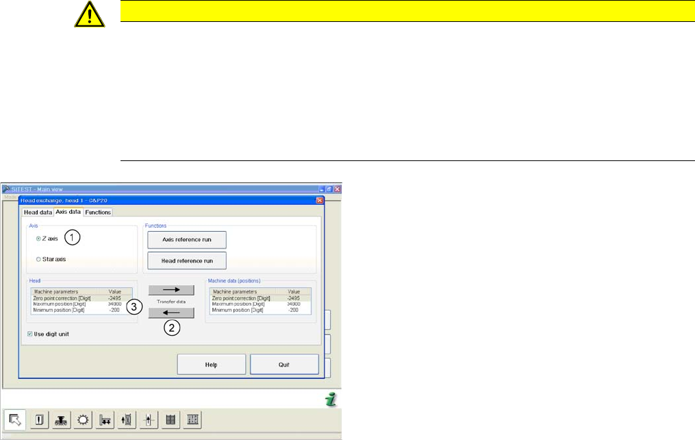
(C&P20 shown as example)
► Start SITEST and select the menu Settings: Head
Exchange: Head for the relevant head.
► Select the Axis data tab
► and enable the setting Z Axis (1).
► Transfer the machine data with the button (2) , from
the list on the right to that on the left (3).