4OM-1003-007.pdf - 第118页
Retainer Cage External Cylinder Shaft V acuum Nozzle (1-8) Pull down the nozzle removal jig to detach the vacuum nozzle. A miniature stroke bearing is used at the nozzle up/ down movement section which consists of the sh…
(1-4) Select the [Designated Hd/Noz Align] button (*3) and press
the [ON] button (entitled "MOVE"). In 2 seconds, press the
[ENABLE] button on the operation panel.
The nozzle is shifted to the position (the front side of the
machine) where it can easily be detached.
To detach a nozzle on the desired head, press the
corresponding [Head #] button.
(1-5) Set the [OPERATION] switch to the "SETUP" side.
Confirm that the "LOCK" lamp on the front operation panel is
"ON"
(1-6) Open the front door.
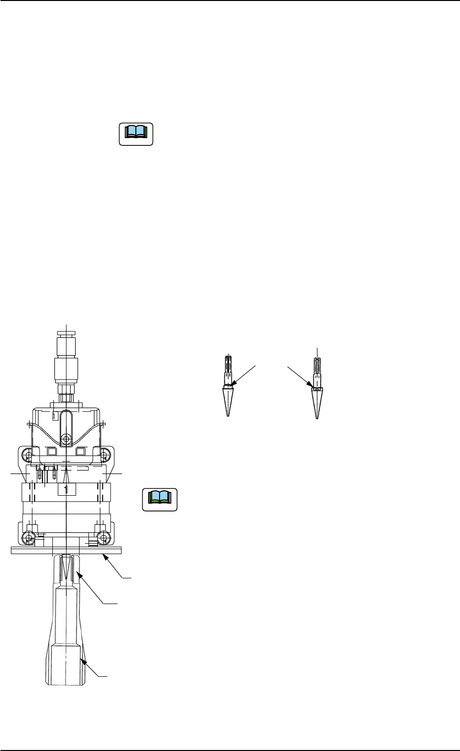
(1-7) Push the bottom of the nozzle removal jig gently and set it on the vacuum
nozzle such that the hook is engaged correctly with the two-plane cham-
fered side of the vacuum nozzle.
(a) While detaching the vacuum nozzle, be careful not
to nick the diffusion plate.
If the nozzle is detached while the nozzle removal jig
is rotating, the diffusion plate may be nicked.
(b) The nozzle removal jig cannot be used for nozzle
type 031 (φ6 nozzle). Detach the nozzle by hand.
1.4 Maintenance Method
0511-002 1-52 AIL01ETRP
Note
Note
Diffusion
Plate
Hook
Nozzle Removal
Jig
Two-Plane
Chamfered Side
(Side View)
(Front View)
Vacuum Nozzle
Fig. 4A65
Fig. 4A65-1
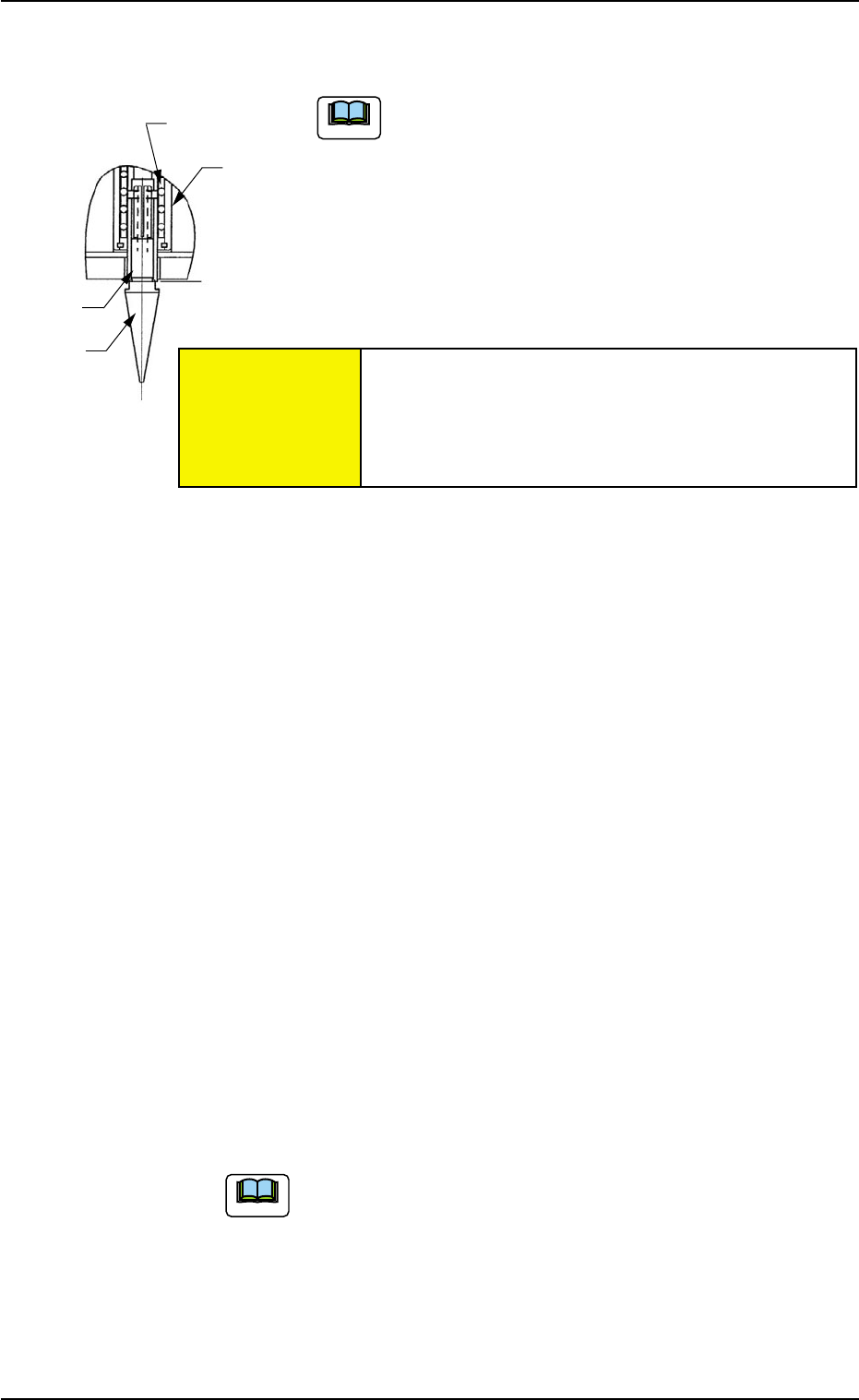
Retainer Cage
External
Cylinder
Shaft
Vacuum
Nozzle
(1-8) Pull down the nozzle removal jig to detach the vacuum nozzle.
A miniature stroke bearing is used at the nozzle up/
down movement section which consists of the shaft,
the retainer cage, and the external cylinder units.
When the section is disassembled by mistake, be
sure to correctly reassemble each unit which belongs
to the section.
When the nozzle is detached, the miniature stroke
bearing and the shaft section should not be removed.
(1-9) Press the [Noz Next] button (*8) and select the nozzle # to
be detached subsequently.
(1-10) Select the [Head #n] button (*7) and press the [ON] button
(entitled "MOVE"). In 2 seconds, press the [ENABLE] button
on the operation panel.
Another nozzle on the same head can be selected.
Repeat the steps, starting with Step (1-7) until all nozzles
are detached from the same head.
(1-11) Select the [Turret Indexing (+)] button (*5) and press the
[ON] button (entitled "MOVE"). In 2 seconds, press the [EN-
ABLE] button on the operation panel.
The rotary turret starts rotating and the subsequent head
moves to the nozzle detachment position.
Repeat the steps, starting with Step (1-7) until all nozzles
are detached from all heads.
When the rotary turret is rotated with a nozzle being
attached, select the [Turret Indexing (-)] button (*6)
and press the [ON] button (entitled "MOVE"). The
rotary turret rotates backward by 1 pitch.
1.4 Maintenance Method
Fig. 4A66
0511-003 1-53
AIL01ETRP
Note
Note
Avoid getting the removed vacuum nozzle
magnetized.
When the nozzle is magnetized, an error will occur
in component pick-up or placement.
CAUTION
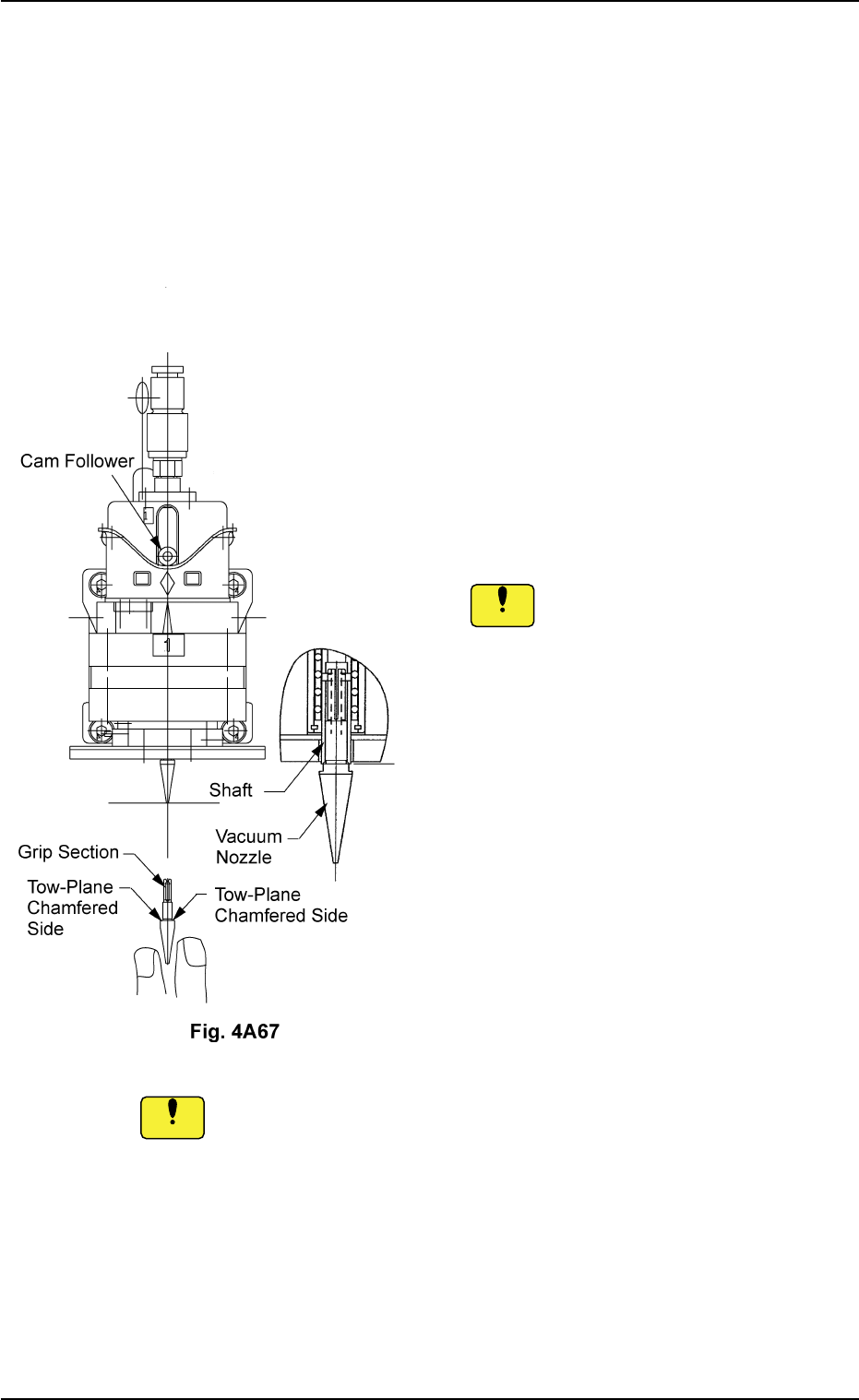
(2) Attachment of Vacuum Nozzle
• Before attaching a vacuum nozzle, check that the end of the nozzle
is not damaged, the tapered section is unscratched, the pick-up hole
unclogged, and the grip section undeformed.
• Select the nozzle which meets the parameters specified in the place-
ment head nozzle data.
(2-1) Move the center shaft of the nozzle position
No. to be attached toward the front side of
the machine.
(2-2) While holding the cam follower with your fin-
ger, orient the two-plane chamfered side
horizontally and insert the vacuum nozzle
over the shaft until it stops.
Inserting a nozzle forcibly over the shaft
in wrong direction deforms the grip
section.
(2-3) Set the [OPERATION] switch to the "RUN"
side.
(2-4) Use the "Head/Nozzle" tab in the "TEACH-
ING" window (submenu) and perform a
teaching operation on the nozzle.
Do not scratch the diffusion plate while attaching a vacuum nozzle.
0511-003 1-54 AIL01ETRP
1.4 Maintenance Method
Notice
Notice