4OM-1003-007.pdf - 第298页
Error ID Item Description 430603 Feeder Set The fdr . mis-set holder ( +) has been detected. 430604 Feeder Set The fdr . mis-set holder ( −) has been detected. 430605 Feeder Set The fdr . mis-set bar ( +) has been detect…
Error ID Item Description
430501 Feeder Carriage Fdr.crg. axis motor #1 & #2 have collided.
(Cause 1) Dirt adheres to the sensor and the optical beam of the sensor is shielded.
(Cause 2) The sensor position may be wrong or the sensor may be defective.
The servo pack may be defective.
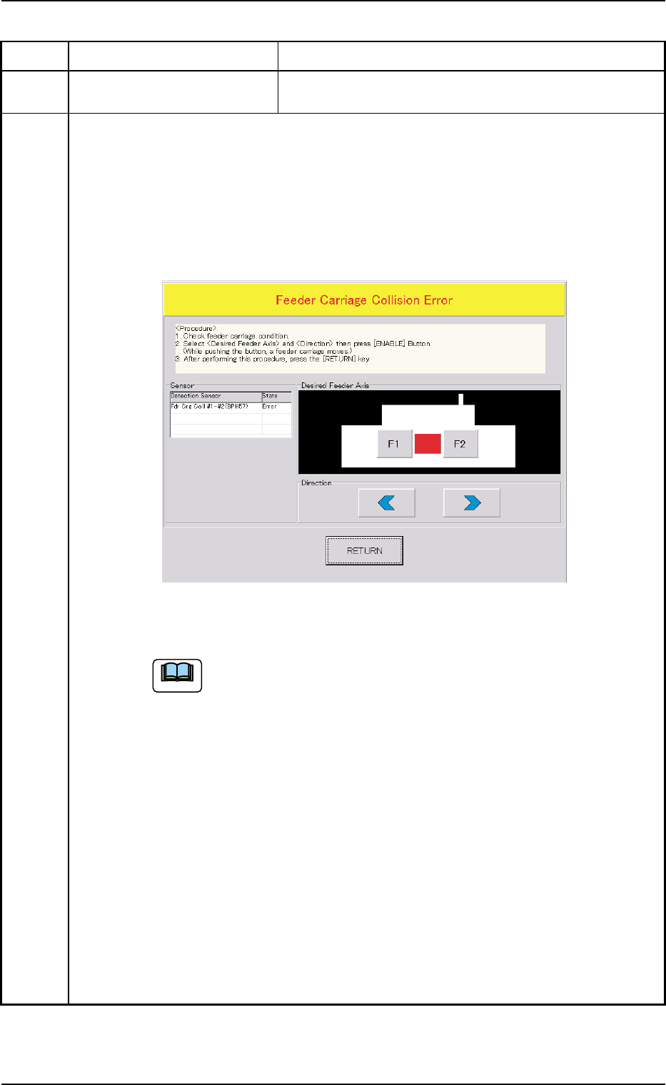
(Remedy 1) When the [RETURN] button is pressed, the "Feeder Carriage Collision Error"
window opens.
Follow the instructions described in this window and the procedure below for the
reset operation.
(a) When the power is re-supplied without following the correct proce-
dure to cancel the error, the feeder carriage collision error will be
detected again and the message will be issued because the contents
of the feeder carriage collision error are backed up.
(b) No zeroing operation can be performed when a feeder carriage colli-
sion error is not canceled completely.
(1) Confirm that there is no error in the feeder carriage section.
(2) Select the object feeder and the direction of the movement. After that, press
the [ENABLE] button to move the feeder carriages in separate directions.
Note: While the [ENABLE] button is held down, the feeder carriages keep
on moving.
(3) After Step (2), press the [RETURN] button.
Ref.: The original window resumes.
(4) Zero all axes and re-start the operation.
(Remedy 2) Contact our service personnel for details.
0309-002 2-102 AIL01ETRP
3.3 Error IDs and Remedial Procedures
Fig. 4B19
Note
Error ID Item Description
430603 Feeder Set The fdr. mis-set holder (+) has been detected.
430604 Feeder Set The fdr. mis-set holder (−) has been detected.
430605 Feeder Set The fdr. mis-set bar (+) has been detected.
430606 Feeder Set The fdr. mis-set bar (−) has been detected.
430607 Feeder Set The fdr. ldx. Lever (+) has been detected.
430608 Feeder Set The fdr. ldx. Lever (−) has been detected.
(Cause 1) The tape feeder is not correctly installed on the feeder carriage.
• The tape feeder was lifted afloat and touches the detection photosensor.
• The tape feeder touched the detection photosensor because it was deformed.
• The tape feeder touched the detection photosensor because it is not for the
TCM-X series.
• The hook of the tape feeder was not locked and the hook or the suppressor
touches the detection photosensor.
• The tape end touched the detection photosensor because it was long.
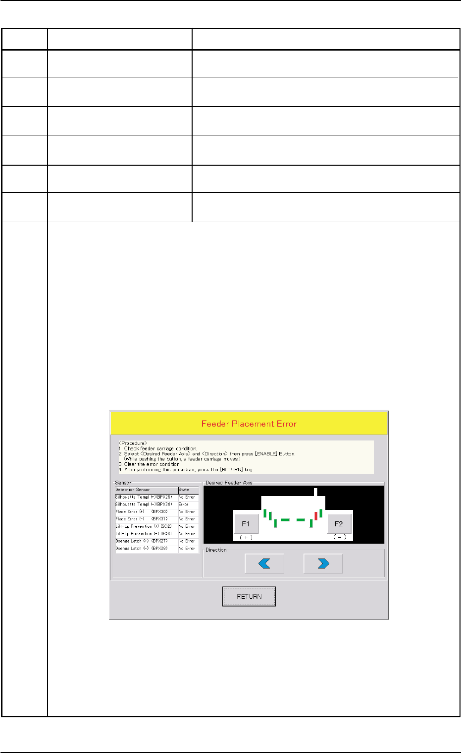
(Remedy 1) When the [RETURN] button is pressed, the "Feeder Placement Error" window
opens.
Follow the instructions described in this window and the procedure below for the
reset operation.
(Continued to the next page)
0305-001 2-103 AIL01ETRP
3.3 Error IDs and Remedial Procedures
Fig. 4B20
Error ID Item Description
(a) When the power is re-supplied without following the correct proce-
dure to cancel the error, the feeder installation error will be detected
again and the message will be issued because the contents of the
feeder installation error are backed up.
(b) No zeroing operation can be performed when a feeder installation
error is not canceled completely.
(1) Confirm that there is no error in the feeder installation sections.
(2) Select the object feeder and the direction of the movement. After that, press
the [ENABLE] button to move the feeder carriage to the position where the
error-caused feeder can be re-installed correctly.
Note: While the [ENABLE] button is held down, the feeder carriages keep
on moving.
(3) Check the cause of the error and re-install the feeder correctly.
(4) Press the [RETURN] button.
Ref.: The original window resumes.
(5) Zero all axes and re-start the operation.
0511-003 2-104 AIL01ETRP
3.3 Error IDs and Remedial Procedures
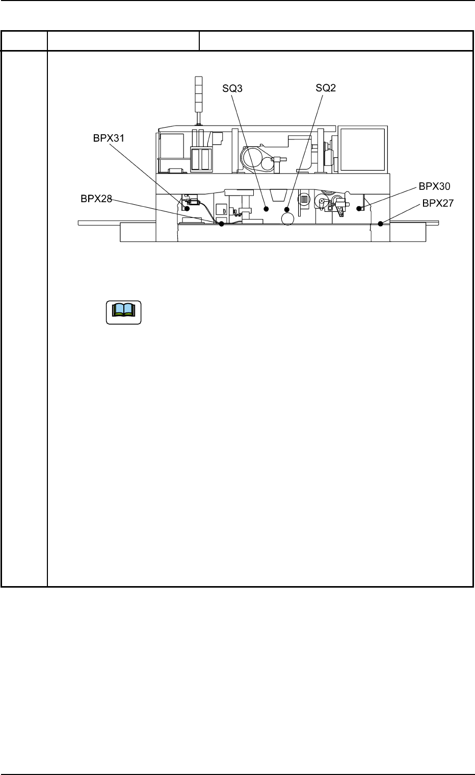
Rear View (Upper Section)
Fig. 4B21 Location of Feeder Installation Error Sensors
Note