4OM-1003-007.pdf - 第31页
Safe-20 AIL01E-P Safety Precautions [FEEDER CARRIAGE COVER] Safety Switch Fig. 1X20 Rear View The [FEEDER CARRIAGE COVER] safety switch is mounted inside the cover as shown below . Fig. 1X21 Switch Name Countermeasures T…

Safe-19 AIL01E-P
Safety Precautions
Table 1X3
Switch Name Countermeasures
(a) When the lamp of the [READY] button is "OFF", the [Work Area
Safety Door] switch is released, making it possible to supply
components.
Confirm that the lamp of the [FEEDER READY] button is "OFF"
and then open the safety door.
(b) When the machine is in the emergency stop mode (load power shut
off), the lamp of the [READY] button extinguishes and the electro-
magnetic lock of the work area safety door is released exception-
ally although the feeder carriage is not located in the work area.
[F1 Work Area Safety Door] Switch
[F2 Work Area Safety Door] Switch
• When the feeder carriage is located in the work
area and the work area safety door in the work
area is opened, the power to drive the feeder
carriage is shut off.
Ref.: The lamp of the [READY] button extin-
guishes.
• When the feeder carriage is not located in the
work area, the [Work Area Safety Door] switch
in the work area is activated, preventing the
safety door from being opened.
Ref.: The lamp of the [READY] button
illuminates.
Should the safety door opens at this time,
the power to drive the feeder carriages (F1
and F2) is shut off.
• While the work area safety door is kept open,
the feeder carriage is prohibited from any move-
ment such as zeroing and manual alignment op-
erations, etc.
Note
0412-001
Safe-20 AIL01E-P
Safety Precautions
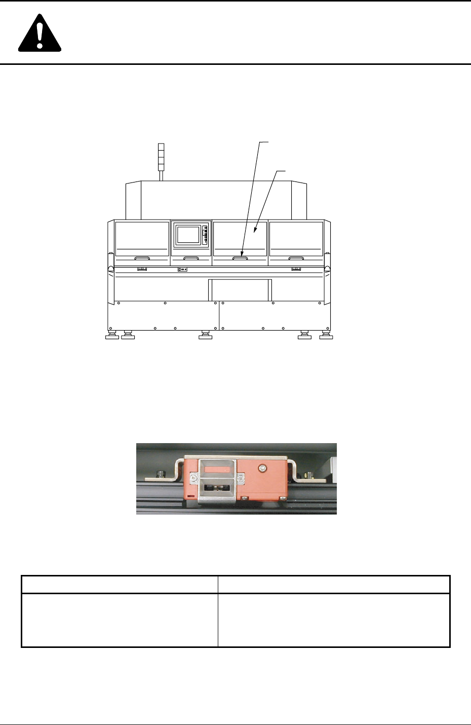
[FEEDER CARRIAGE COVER] Safety Switch
Fig. 1X20 Rear View
The [FEEDER CARRIAGE COVER] safety switch is mounted inside the cover as
shown below.
Fig. 1X21
Switch Name Countermeasures
Table 1X4
[FEEDER CARRIAGE COVER] Safety
Switch
• The power for operations cannot be supplied
with the feeder carriage cover being open.
[FEEDER CARRIAGE COVER]
Safety Switch
Feeder Carriage Cover
0412-001
Safe-21 AIL01E-P
Safety Precautions
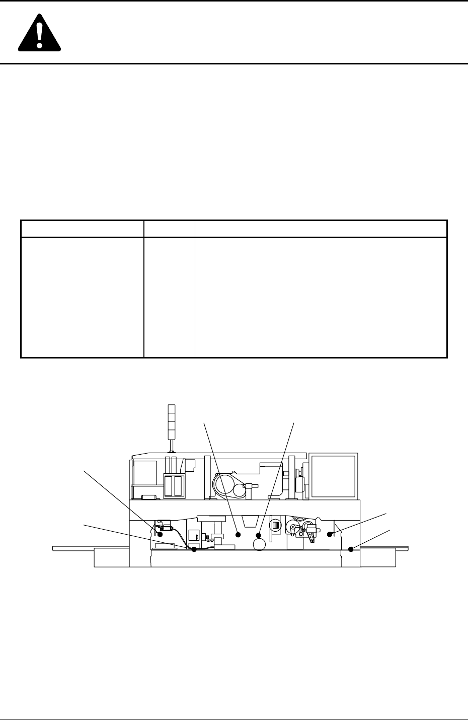
Module Protection Sensors
Feeder Installation Error Detection Sensors
When a tape feeder is not installed correctly, these sensors are used to prevent the
machine from being operated.
Table 1X5
Sensor Name Symbol Countermeasures
Installation Error (+) BPX30
Installation Error (-) BPX31
Lifting Prevention (+) SQ2
Lifting Prevention (-) SQ3
Disengaged Latch (+) BPX27
Disengaged Latch (-) BPX28
Fig. 1X22 Feeder Installation Error Detection Sensors
When one of the left sensors has detected an error,
the following measures are taken.
• The power to drive Feeder Carriages #1 and #2 is
shut off.
• The rotary turret stops after a cycle of operation.
Ref.: The rotary turret stops with its angle at 0° or
360°.
BPX28
BPX31
SQ3
SQ2
BPX30
BPX27
Rear View (Upper Section)
0412-001