4OM-1003-007.pdf - 第402页
5.3 T roubleshooting on Placement Errors 5.3.1 Cause and Remedy of Placement Errors (1) Positional and Angular Deviations of Component Placement (1-1) Situational Grasp of Error Generation Positional and angular deviatio…
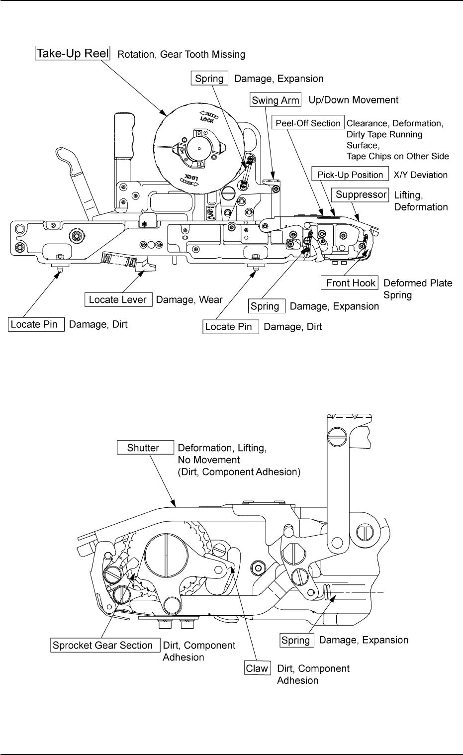
• Checkpoints on Tape Feeder
0305-001 2-213
AIL01ETRP
Fig. 4B33
Fig. 4B34
5.2 Troubleshooting on Pick-Up Errors
5.3 Troubleshooting on Placement Errors
5.3.1 Cause and Remedy of Placement Errors
(1) Positional and Angular Deviations of Component Placement
(1-1) Situational Grasp of Error Generation
Positional and angular deviations may be generated in either Process
C or D and E.
See Fig. 4B29.
By placing a component on the P.C.B. where a double-faced adhesive
tape is affixed, it can be checked and determined in which process
positional and angular deviations are generated.
When a positional deviation is generated on the double-faced tape, it
indicates that positional and angular deviations occur in Process C.
When no positional deviation is generated, it means that positional and
angular deviations occur in Process D or E.
(1-2) Positional and Angular Deviations in Process C
When a positional deviation is generated due to the movement of the
head after component recognition or a rotational deviation by place-
ment angle correction, the deviation may be caused mainly by the fol-
lowing two factors.
• Deterioration of Vacuum Suction Force
• Vibration or Shock during Nozzle (Head) Movement
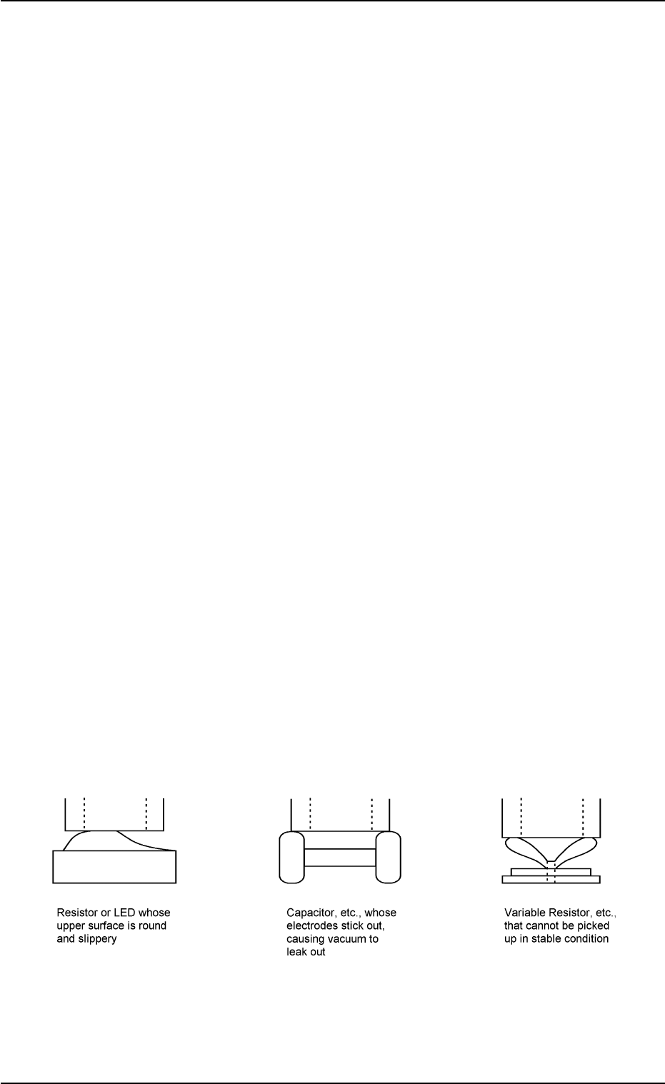
When one of the above factors exists, unstable components (compo-
nents that cannot be picked up in stable condition) such as those shown
in Fig. 4B35 are directly affected.
When a positional deviation is generated on the components (the com-
ponents of the same type that have been used in the past actual pro-
duction), check for the above-described factors.
As for vacuum suction force, check the nozzle and the vacuum line.
As for vibration during nozzle movement, check the related spots in the
range of Process C.
Fig. 4B35 Easily-Dislocated Components during Place-
ment (Example 1)
0305-001 2-214
AIL01ETRP
5.3 Troubleshooting on Placement Errors
(1-3) Positional and Angular Deviations in Process D or E
When a positional deviation is not generated on the double-faced tape,
it indicates that positional or angular deviation occurs in Process D or
E.
As a phenomenon at this time
• The component is dislocated right after it is placed.
• The component is dislocated during operation subsequent to the place-
ment.
• The component is dislocated during P.C.B. discharge operation sub-
sequent to the placement.
The causes in the above cases lie in the factors affected commonly by
the shape of the component, the condition of the P.C.B., or the condi-
tion of solder paste or glue.
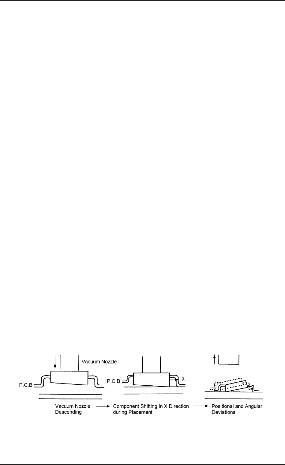
Fig. 4B36 is an example, which shows that a component is dislocated
right after it is placed due to the upper and lower surfaces of the com-
ponent not parallel to each other.
A force is generated and moves the component in the X direction at the
moment when the lower surface touches the P.C.B. during placement.
This leads to the positional and angular deviation of the component
placement.
When this type of component is used, this failure may be avoided by
slowing down the placement speed or slightly increasing the nozzle
descent level for the placement.
Some components may be dislocated easily during X/Y table move-
ment or P.C.B. discharge operation after they are placed.
The factor may be weak holding power of solder paste or glue or im-
perfect fixation of P.C.B.
It is required to check these conditions and take individual counter-
measures.
Fig. 4B36 Easily-Dislocated Component during Placement (Example 2)
0305-001 2-215
AIL01ETRP
5.3 Troubleshooting on Placement Errors