5OM-1348-002_w.pdf - 第159页
5-B 0606-001

5-A
0606-001
第五章
电线连接图
本章节就各部的电线连接图进行说明。
因含有一定的难度,参考时请充分注意。

5-B0606-001
5-1
&38ݚ䚽䖳䌙᭮
0606-001 B(M829JSB---0001)
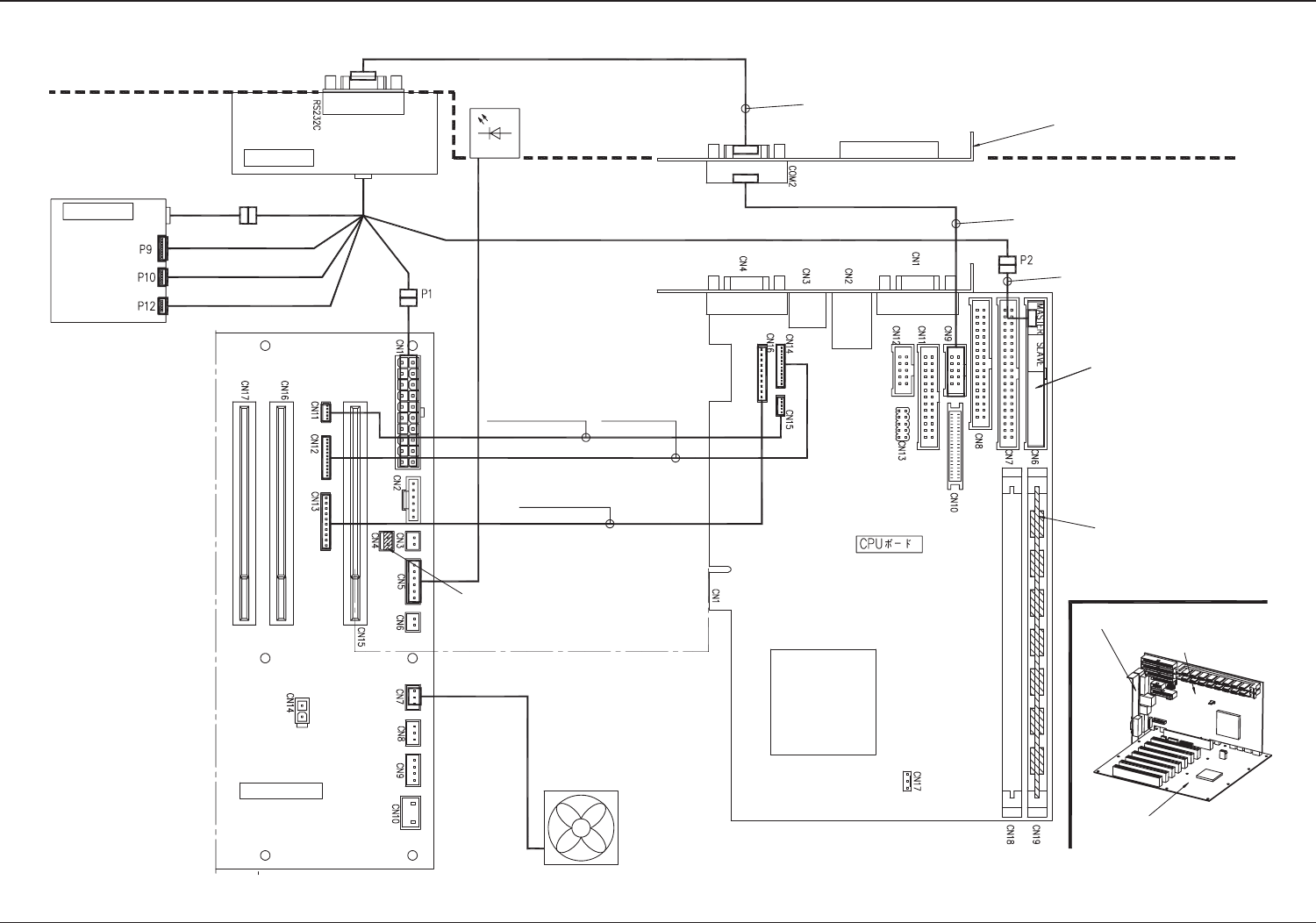
&38ݚ䚽䖳䌙᭮
Power Unit
Battery Unit
Case LED
Back Plane
Charge and Discharge
Connector
The jumper (accessory part)
is connected to the back plane.
EXT Connector Cable
PAT-092
(provided together
with CPU board)
Provided together with BL)159
Provided together with BL)156
Memory (Provided)
CPU Board
COM2 Drawer Panel
Back Plane
Case Fan
RESET Board Connector
Cable
PAT-311 (provided together
with CPU board)
COM2 Drawer Panel
RAS Board Connector Cable
PAT-309 (provided together
with CPU board)
BL) 156: 630 141 4287
BL) 159: 630 125 6498
BL) 158: 630 126 9856