00195044-22_UM_VisionTeachStation_5.x.x_DE_EN.pdf - 第100页
1 Overview Vision Teach Station 5.x.x User Manual 1.1 Description 05/2019 Edition 8 The vision teach sta tion essentially consists of the following components: – Base module with electronic circ uits and compone nt camer…
Vision Teach Station 5.x.x User Manual 1 Overview
05/2019 Edition
7
1 Overview
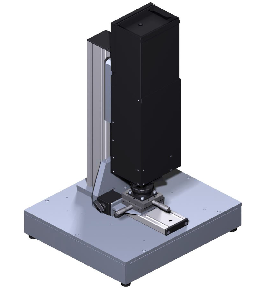
This document describes the Vision Teach Station Version 5.x.x. The vision teach station is a
system for creating and testing package form descriptions for components to be processed on SI-
PLACE
®
placement machines.
1
Fig. 1.0 - 1 Vision teach station with type 33 component camera

1 Overview Vision Teach Station 5.x.x User Manual
1.1 Description 05/2019 Edition
8
The vision teach station essentially consists of the following components:
– Base module with electronic circuits and component camera (see Fig. 1.0 - 1
, page 7)
– PC (Recommendation as of 2019: SIMATIC IPC 647C)
Preinstalled operating system Windows 7 (64-bit) or Windows 10 (64-bit) 1
SIPLACE vision image processing software 1
SIPLACE Pro database server 1
2 x PCI for camera interfaces: CAN bus card and camera bus card 1
The hotlink driver and CAN bus card driver will be installed with the Vision Teach Station soft-
ware. 1
The possible configurations are described in chapter 3
.
1.1 Description
The vision teach station is used to create and test descriptions for package forms for any place-
ment machine and to run component inspections.
The package form descriptions thus created may be stored in the SIPLACE Pro database on the
vision teach station and transferred to the SIPLACE Pro database of the production system. You
also have the option of loading vision measurement contexts from placement machines to the vi-
sion teach station, where they can be analyzed. Only multiple component measurements are not
yet possible on the placement machine.
1.2 Advantages
The major advantage of this offline system is that it is totally independent of the production system,
and no production system resources have to be used for creating and testing package form
descriptions. As a result, there is no loss of productivity due to the description and testing of
package forms. The time taken to introduce new products can also be considerably reduced with
this independent system.

Vision Teach Station 5.x.x User Manual 1 Overview
05/2019 Edition 1.3 Which component cameras are supported?
9
1.3 Which component cameras are supported?
The vision teach station supports the following component cameras:
1
Component cameras supported by the vision teach s 1
Component camera Component range Used on which placement machine?
C&P, type 23, 6x6 ,
digital
01005 to 6 x 6 mm²
X series:
Head camera for the C&P20 head
C&P, type 28, 18 x 18,
digital
0402 to 18 x 18 mm²,
PLCC 44 including BGA, µBGA,
flip-chip, TSOP, QFP,
SO to SO32, DRAM
X/D series:
Head camera for the C&P12 head
C&P, type 29, 27 x 27,
digital
0201 to 27 x 27 mm²
PLCC, SO, QFP, TSDP, SOT,
MELF, CHIP, IC, BGA
X/D series:
Head camera for the C&P6 and C&P12
heads
C&P, type 30, 27 x 27,
digital
01005 to 27 x 27 mm²
PLCC, SO, QFP, TSDP, SOT,
MELF, CHIP, IC, BGA
X/SX/D series:
Head camera for the CPP and C&P12
heads
P&P, stationary, type 33,
55 x 45, digital
0402 to 55 x 45 mm²,
MELF, SO, PLCC, QFP,
electrolytic capacitors, BGA,
connectors
X/D series:
Stationary camera for ICs and connec-
tors
P&P, stationary, type 25,
16 x 16, digital
0201 to 16 x 16 mm²,
SO, PLCC, QFP, sockets, plugs,
BGA, special components, bare
dies, flip-chips, shields
X/D series:
Stationary camera for flip-chip compo-
nents
P&P, stationary, type 36,
32 x 32, digital
(Is supported from SIPLACE
Pro 4.1 onwards)
0603 to 32 x 32 mm²
SO, PLCC, QFP, BGA, special
components, bare die, flip-chip
D1:
Stationary camera for ICs
C&P, type 41, 6x6,
digital
03015 to 6.5 x 6.5 mm², Melf,
SOT, SOD, bare die, flip-chip
X/SX-Serie:
Head camera for C&P20 heads