00195044-22_UM_VisionTeachStation_5.x.x_DE_EN.pdf - 第130页
5 Installing the cameras Vision Teach Station 5.x.x User Manual 5.2 Installing head cameras, type 28, 29 and 30 05/2019 Edition 38 5.2 Installing head came ras, type 28, 29 and 30 The 28 ,29 and 30 type head came ras are…
Vision Teach Station 5.x.x User Manual 5 Installing the cameras
05/2019 Edition 5.1 Installing stationary cameras, type 25, 33 and 36
37
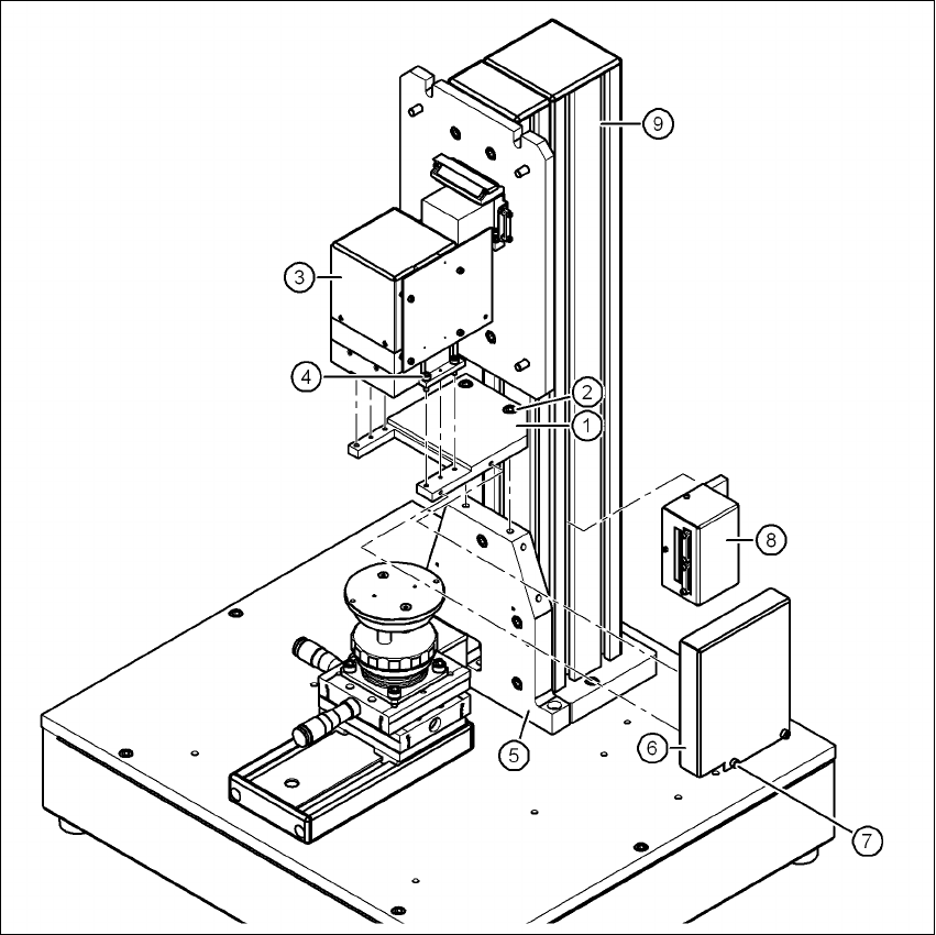
Key to figure 5.1 - 7, page 36
(1) Camera, type 33, 36 or 25
(2) Mount, type 33/36 or 25
(3) Mounting plate
(4) Pillar
(5) Hexagon socket head screw M6 x 20, 4x
(6) X2: CAN bus connection for stationary camera
(7) X1: Power supply connection for stationary camera
(8) Hexagon socket head screw M3 x 8, 2x
(9) Component support, camera type 25/33/36, complete
(10) Holder for component support
(11) Cable ties, 3x
(12) Magnetic switch
(13) Positioning unit
5
5.1.3 Connecting camera type 33, 36 or 25
CAUTION 5
Make sure that the base module and PC are switched off before connecting any cables.
Connect connector X2 on cable 03040355-W2 to socket X2 (item 6 in Fig. 5.1 - 7, page 36) on
the base module.
Connect connector X1 on cable 03040355-W1 to socket X1 (item 7 in Fig. 5.1 - 7, page 36) on
the base module.
Plug the camera bus cable 03040359-xx into the RJ45 socket on the camera (item 2 in Fig. 5.1
- 2, page 31).
Connect the other end of the camera bus cable to the camera bus interface on the PC (item 1
in Fig. 4.3 - 2
, page 27).
Fix the cables 03040355, W1 + W2 and 03040359-xx to the pillar using 3 cable ties
(item 11 and item 4 in Fig. 5.1 - 7
, page 36).
Make sure that the bending radii of the cables are large enough and that there is little tension
so that the cables are not damaged.

5 Installing the cameras Vision Teach Station 5.x.x User Manual
5.2 Installing head cameras, type 28, 29 and 30 05/2019 Edition
38
5.2 Installing head cameras, type 28, 29 and 30
The 28 ,29 and 30 type head cameras are intended for the 12-segment Collect&Place head and
the CPP head.
The 6-segment Collect&Place head is equipped with the 29 type component camera.
The three cameras have the same mechanical and electrical interfaces. The installation steps are
described with reference to camera type 28.
5.2.1 Tools required
Allen key, set
5.2.2 Fitting the camera to the mounting plate
Fit the mount (item 1 in Fig. 5.2 - 8, page 31) to the mounting plate (item 5 in Fig. 5.2 - 8, page
31
) using the two hexagon socket head screws M6 x 12 (item 2 in Fig.
5.2 - 8
, page 31).
Place the camera (item 3 in Fig. 5.2 - 8, page 31) on the mount (item 1 in Fig. 5.2 - 8, page 31)
so that the two parallel pins of the camera slide into the holes in the mounting plate and so that
the camera lies flat on the mounting plate.
Use the four hexagon socket head screws M4 x 12 (item 4 in Fig. 5.2 - 8, page 31) to fit the
component camera (item 3 in Fig. 5.2 - 8
, page 31).
NOTE
With camera type 29, the wire management mount (item 3 in Fig. 5.2 - 9
) butts against the alu-
minum profile during assembly. In this case, remove the bracket from the camera together with
the wire management mount. 5
Vision Teach Station 5.x.x User Manual 5 Installing the cameras
05/2019 Edition 5.2 Installing head cameras, type 28, 29 and 30
39
5
Fig. 5.2 - 8 Installing camera type 28
(1) Mount for camera type 28/29
(2) Hexagon socket head screw M6 x 12, 2x
(3) Camera type 28
(4) Hexagon socket head screw M4 x 12, 4x
(5) "Bottom" mounting plate"
(6) Cover for camera type 28/29
(7) Hexagon socket head screw M4 x 8, 2x
(8) Adapter for head camera
(9) Pillar