00195044-22_UM_VisionTeachStation_5.x.x_DE_EN.pdf - 第135页
Vision Teach Station 5.x.x User Manual 5 Installing the cameras 05/2019 Edition 5.2 Installing head cameras, type 28, 29 and 30 43 (7) Connection for cable, he ad camera 1 (03040353-W1: 26-pin, 03040353-W2: 12 -pin) (8) …
5 Installing the cameras Vision Teach Station 5.x.x User Manual
5.2 Installing head cameras, type 28, 29 and 30 05/2019 Edition
42
5
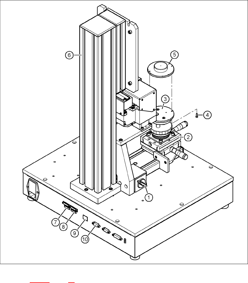
Fig. 5.2 - 10 Base module with camera type 28
Key to fig. 5.2 - 10, page 42
(1) Magnetic switch
(2) Positioning unit
(3) Holder for component support
(4) Hexagon socket head screw M3 x 8, 2x
(5) Component support, camera type 28/29
(6) Pillar

Vision Teach Station 5.x.x User Manual 5 Installing the cameras
05/2019 Edition 5.2 Installing head cameras, type 28, 29 and 30
43
(7) Connection for cable, head camera 1 (03040353-W1: 26-pin, 03040353-W2: 12-pin)
(8) Connection for cable, head camera 2 (03040353-W1: 26-pin, 03040353-W2: 12-pin)
(9) Connection for camera bus cable to the PC (03040359-xx)
(10) Connection for CAN bus cable to the PC (03040362-xx)
5.2.5 Connecting the adapter, base module and PC
Connect the camera bus connection on the base module (item 9 in Fig. 5.2 - 10, page 42) to
the card for the camera bus interface in the PC (item 1 in Fig. 4.3 - 2
, page 27) with the cable
03040359-xx.
Connect the CAN bus connection on the base module (item 10 in Fig. 5.2 - 10, page 42) to the
interface card in the PC (item 2 in Fig. 4.3 - 2
, page 27) with cable 03040362-xx.

5 Installing the cameras Vision Teach Station 5.x.x User Manual
5.3 Installing the type 23 head camera 05/2019 Edition
44
5.3 Installing the type 23 head camera
The type 23 head camera is the component camera for the 20-segment Collect&Place head.
5.3.1 Tools required
Allen key, set
5.3.2 Fitting camera type 23 to the mounting plate
Fit the mount (item 3 in Fig. 5.3 - 11, page 45) to the mounting plate (item 7 in Fig. 5.3 - 11,
page 45
) using the two hexagon socket head screws M6 x 12 (item 4 in Fig. 5.3 - 11, page 45).
Place the camera (item 1 in Fig. 5.3 - 11, page 45) on the mount (item 3 in Fig. 5.3 - 11, page
45
) so that the two parallel pins of the camera slide into the holes in the mounting plate and so
that the camera lies flat on the mounting plate.
Use the four hexagon socket head screws M3 x 12 (item 2 in Fig. 5.3 - 11, page 45) to fit the
component camera (item 4 in Fig. 5.3 - 11
, page 45).